Step-by-Step Assembly Guidance#
We provide step-by-step assembly guidance for JoyLo. Assembly videos can be found in Assembly Videos.
Prepare All Components#
First, prepare all components listed in the BoM. Download the OBJ files for 3D printing the JoyLo arm links:
Shoulder mount
mount.obj(link)Shoulder rear mount
mountback.obj(link)Shoulder roll link
l2.obj(link)Shoulder coupling rod
l2back.obj(link)Upper arm
l3.obj(link)Elbow
l4.obj(link)Forearm
l5.obj(link)JoyCon enclosure
jcA.obj(link)JoyCon finger holder
jcB.obj(link)JoyCon main link
jcC.obj(link)JoyCon spacing bar
jcSpace_33mm.obj(link)U2D2 mount
u2d2_mount.obj(link)
Note that all arm links are designed for the right arm. Simply mirror the links to create the left arm.
Note
If you would like to modify our design, you can download editable F3D files here.
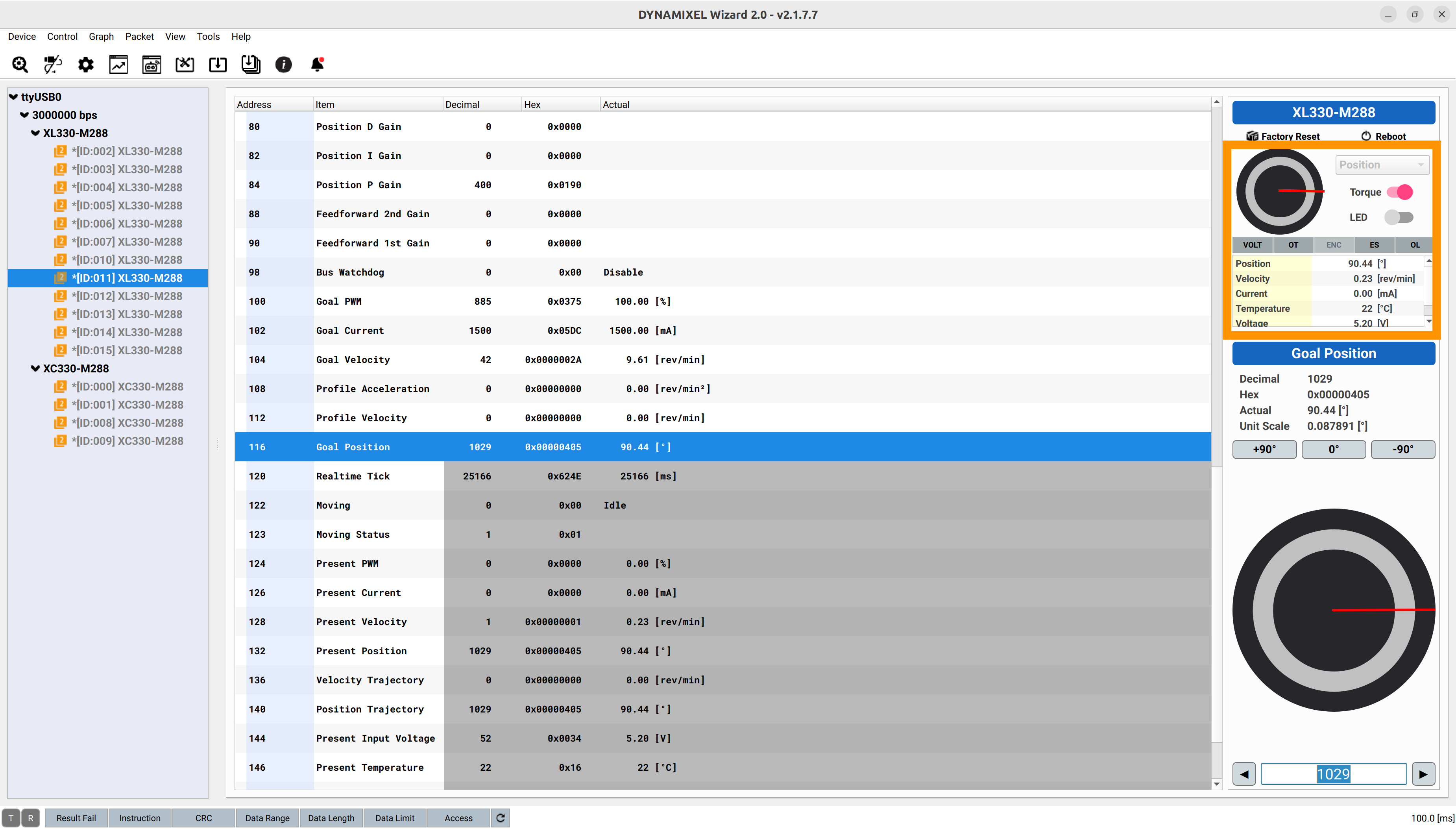
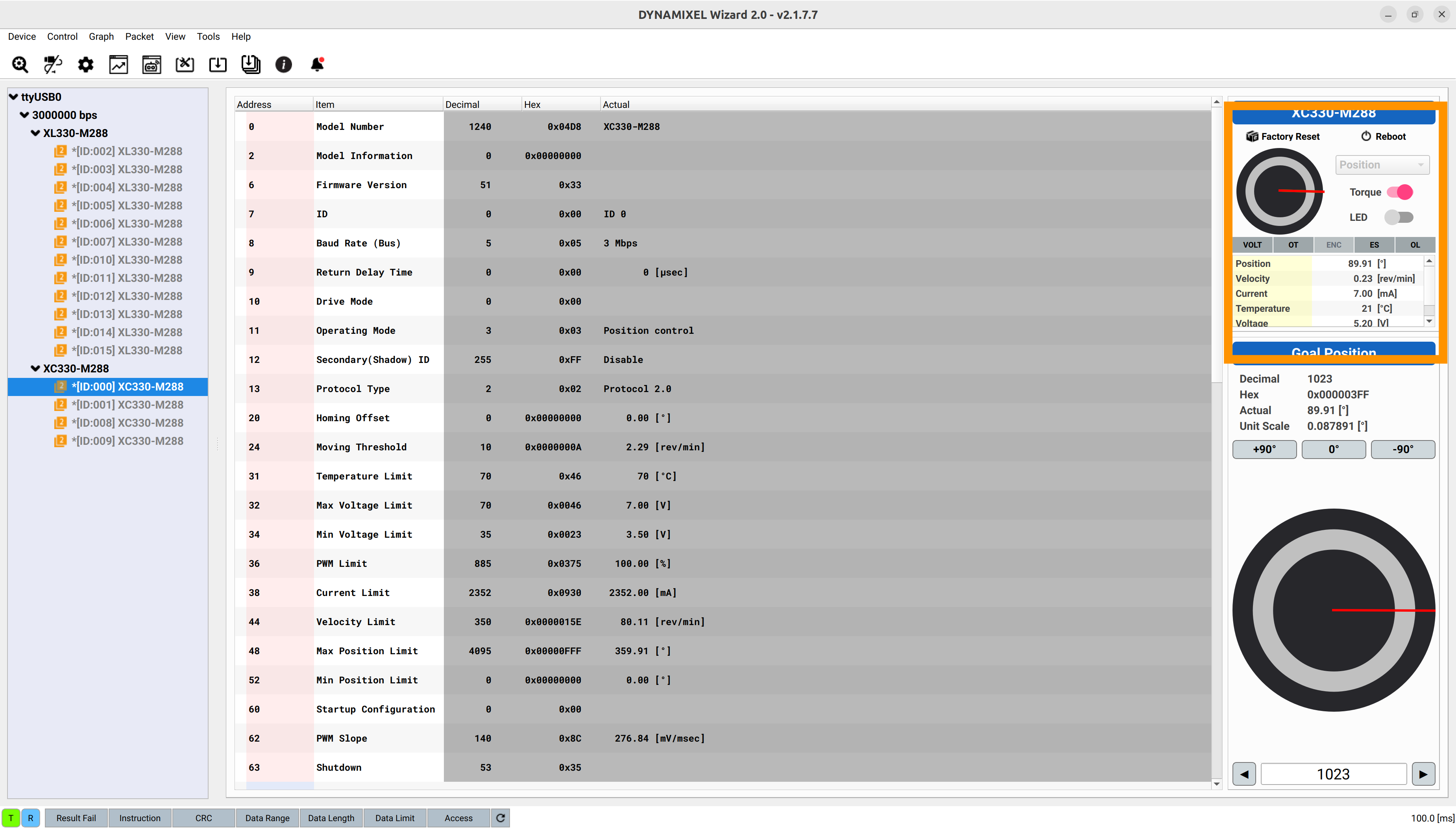
Prepare the Dynamixel Software#
We assign unique motor IDs and tune default shaft positions during the assembly. To do this, install Dynamixel Wizard and ensure it can detect motors by following the instructions here.
Assemble the Right Arm#
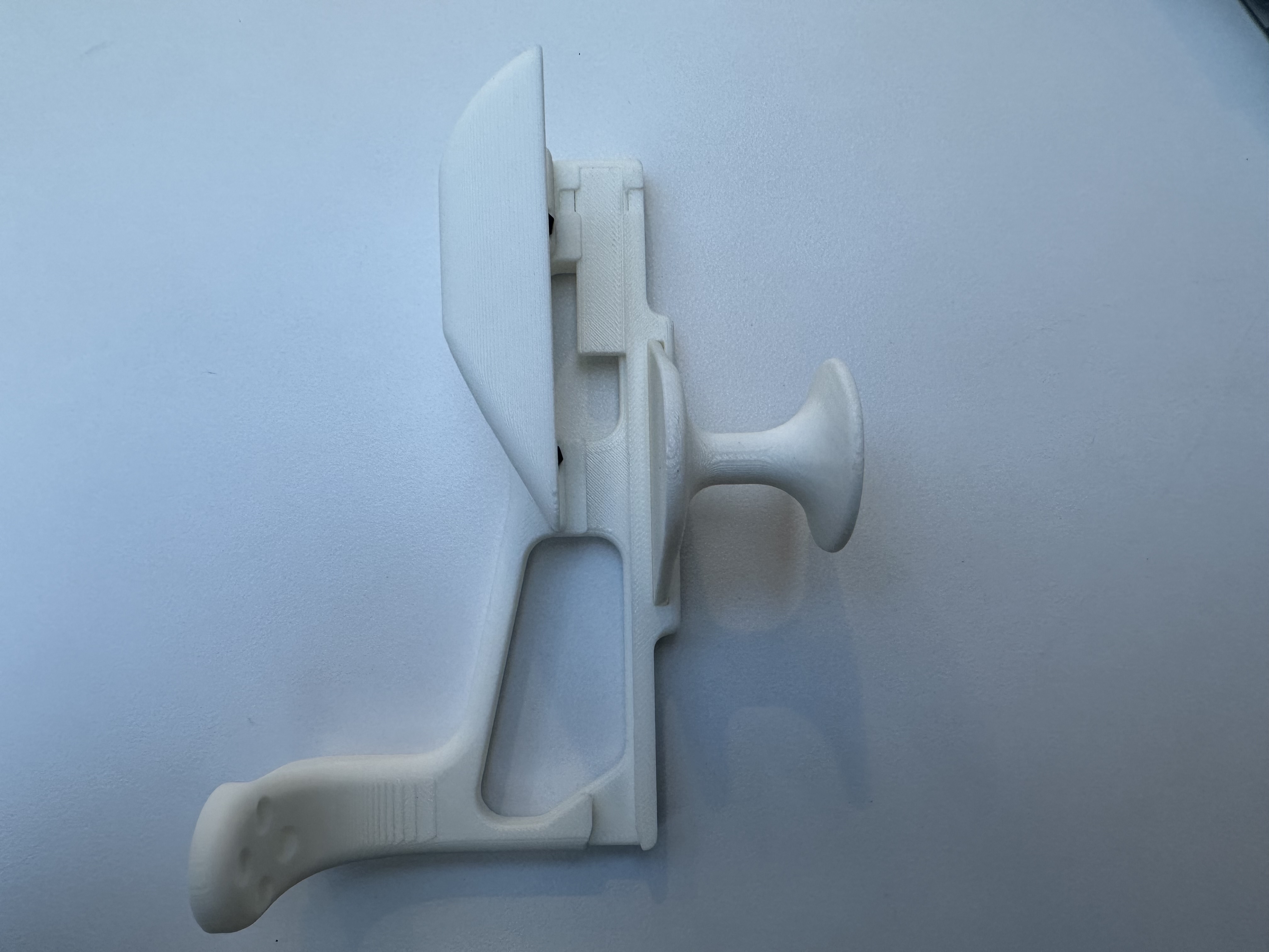
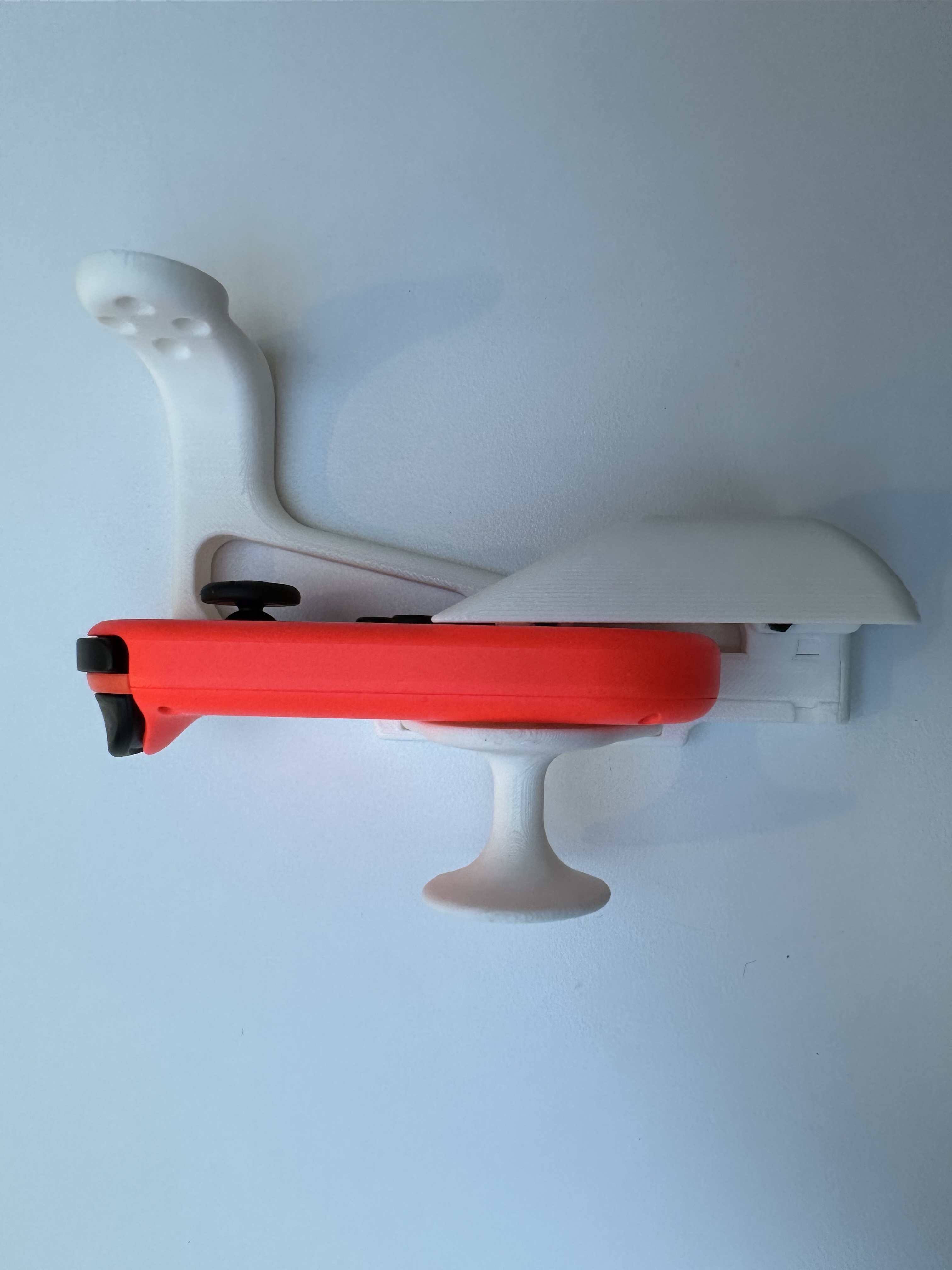
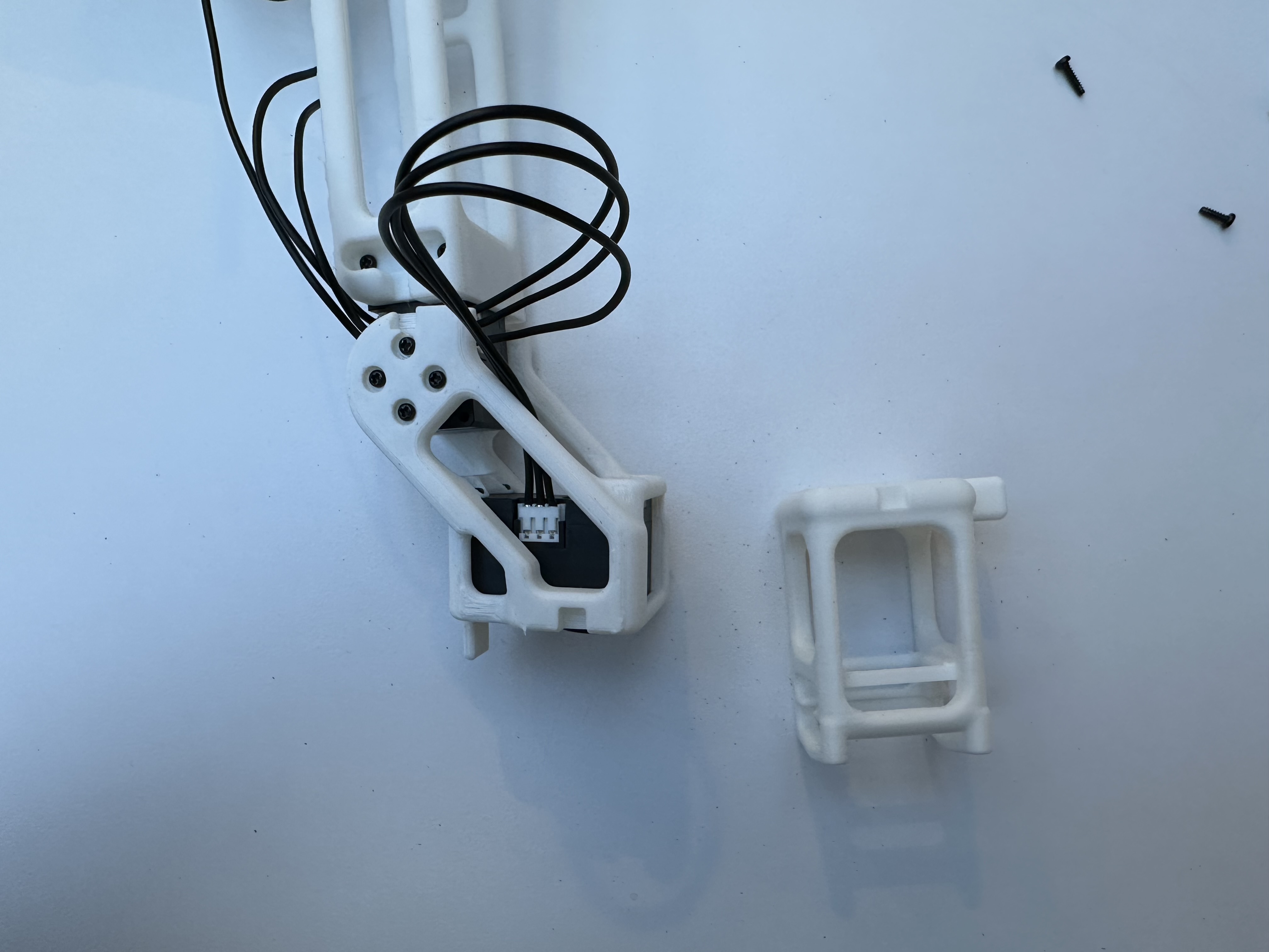
JoyCon Holder#
Take the JoyCon main link jcC.obj and spacing bar jcSpace_33mm.obj, as shown below.
Insert the spacing bar into the slot of the main link.
Take the JoyCon enclosure jcA.obj, two M2 screws, and two nuts.
Insert the nuts into the enclosure. Tighten the screws to secure the enclosure to the main link.
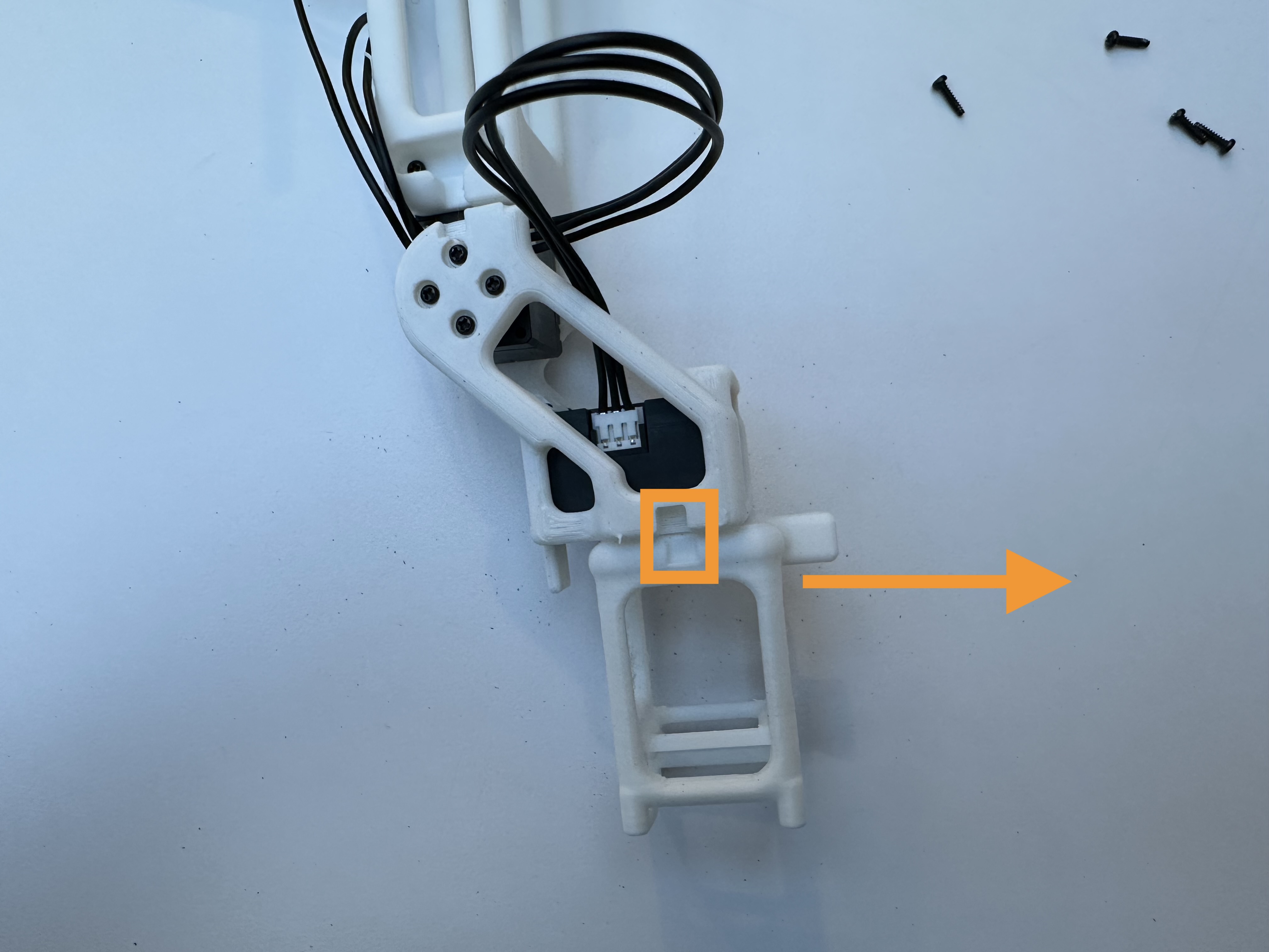
Take the JoyCon finger holder jcB.obj.
Insert the finger holder into the main link, and make sure the right JoyCon can be slid in.
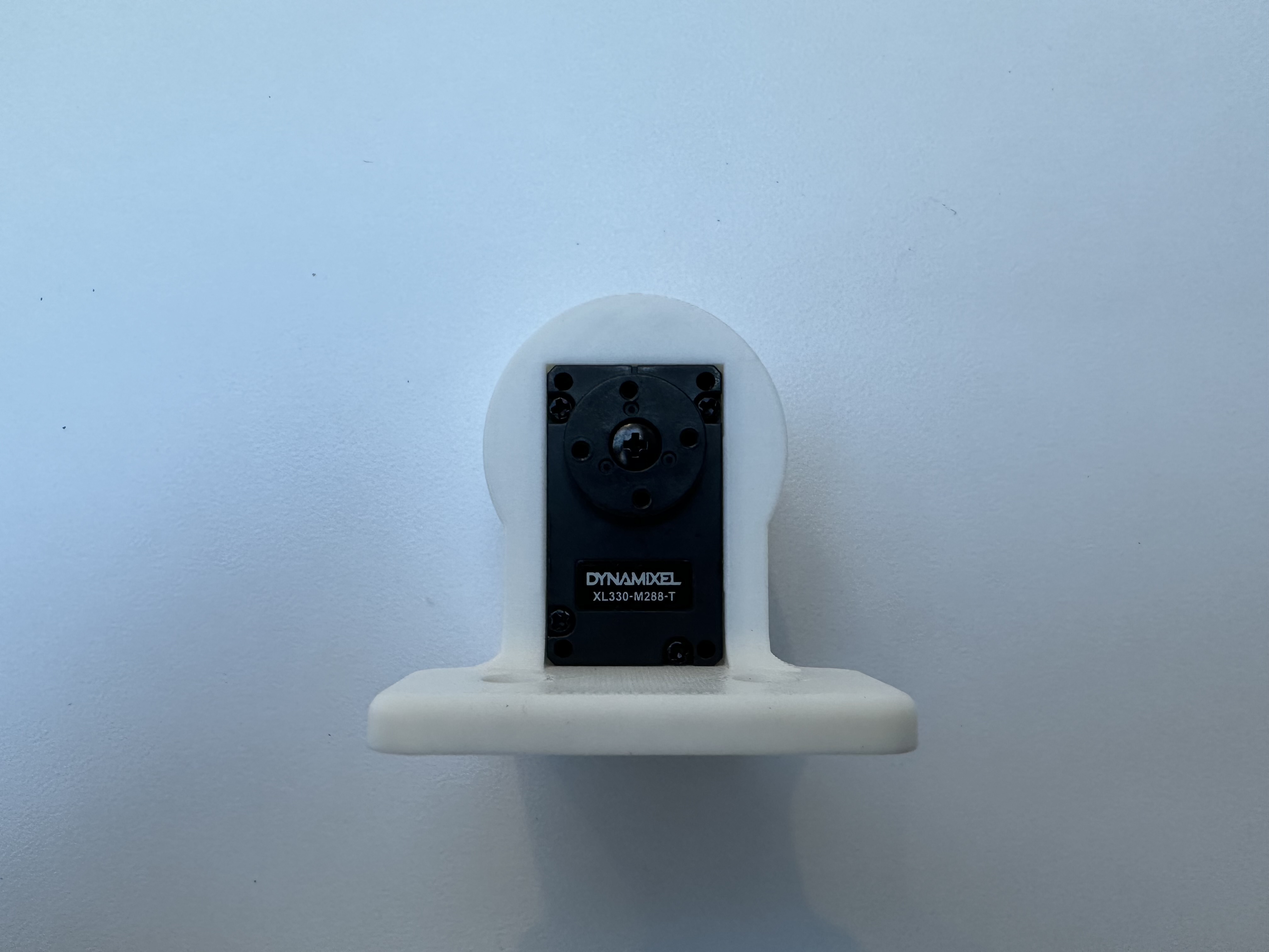
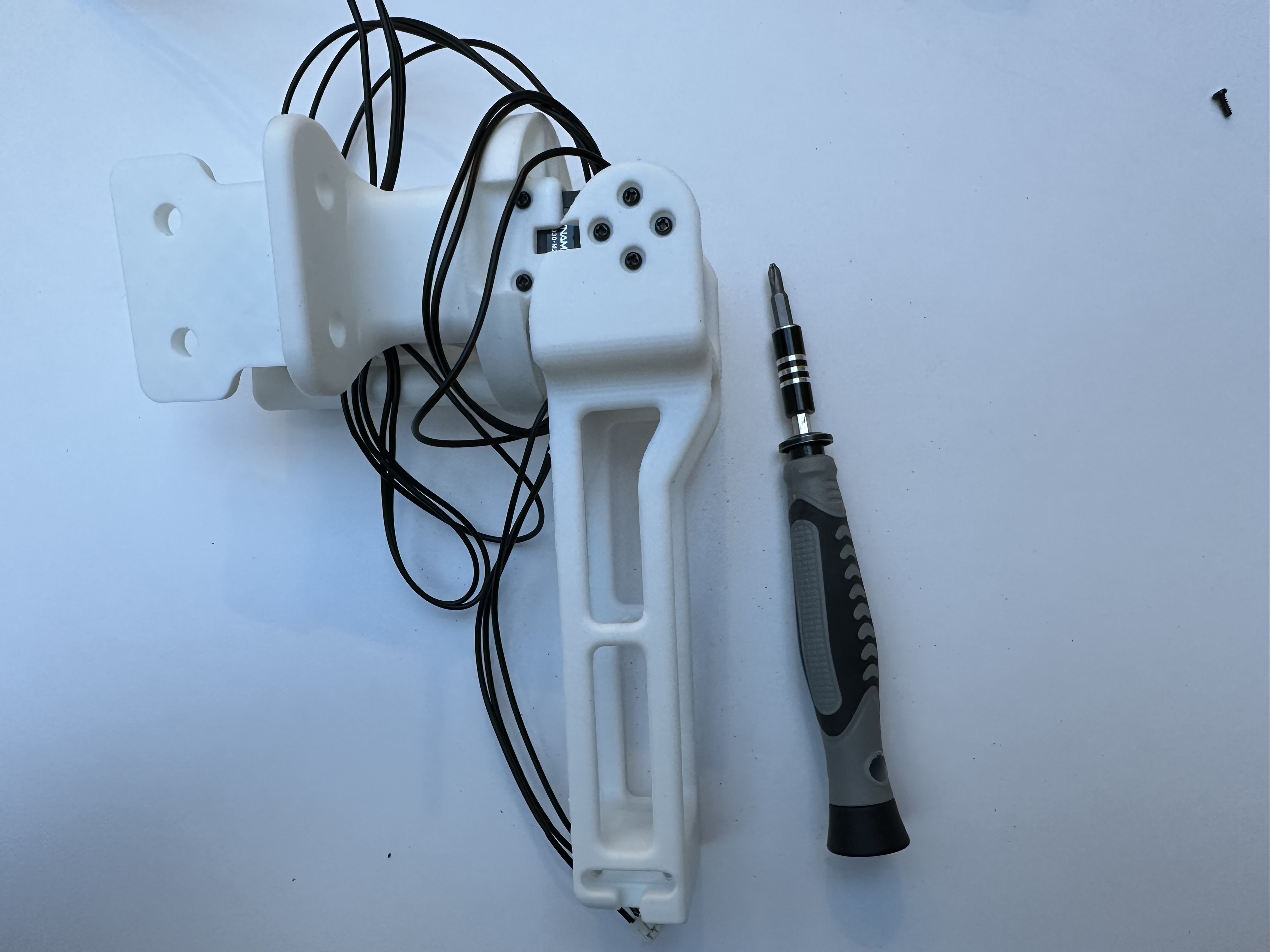
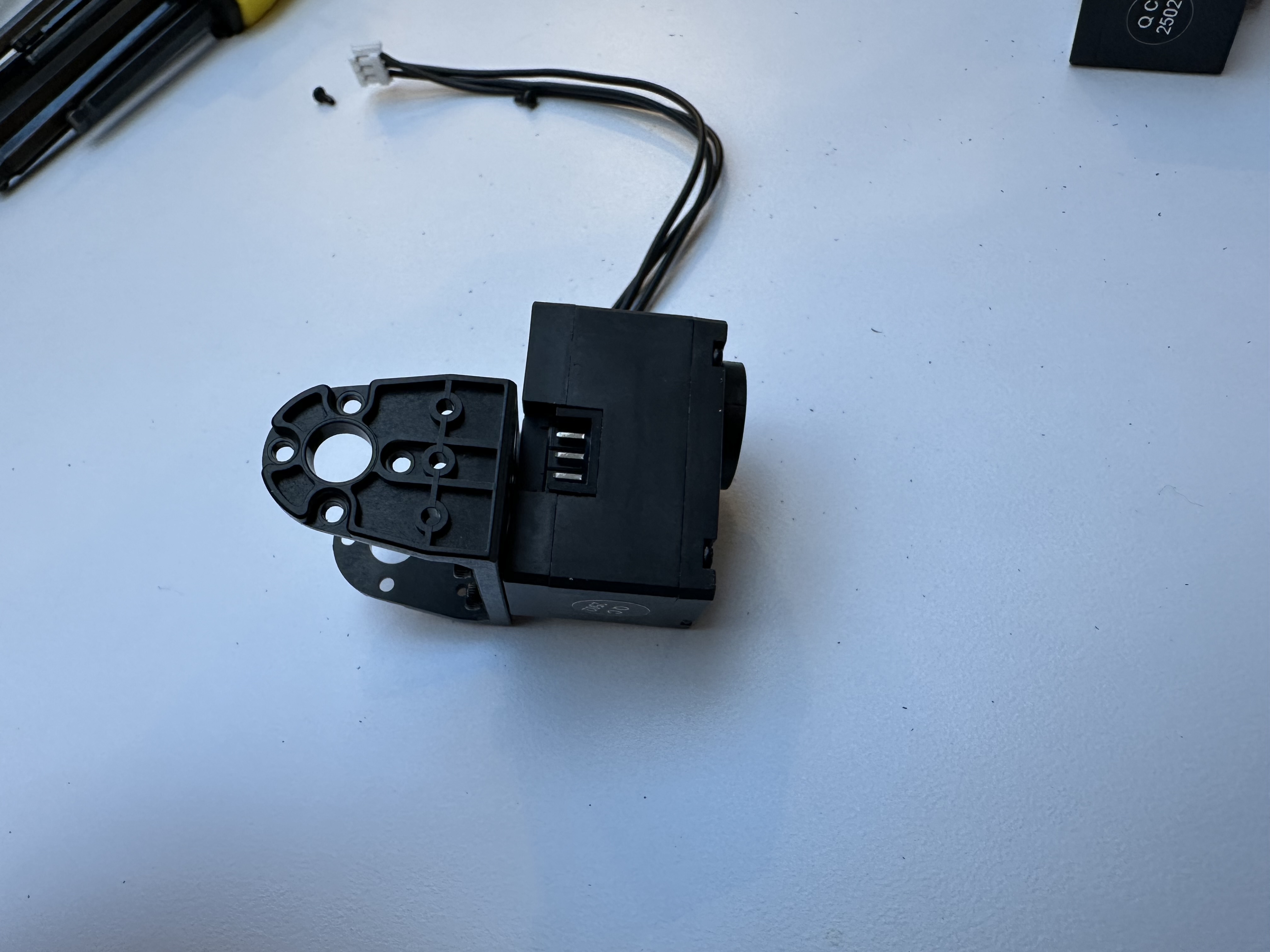
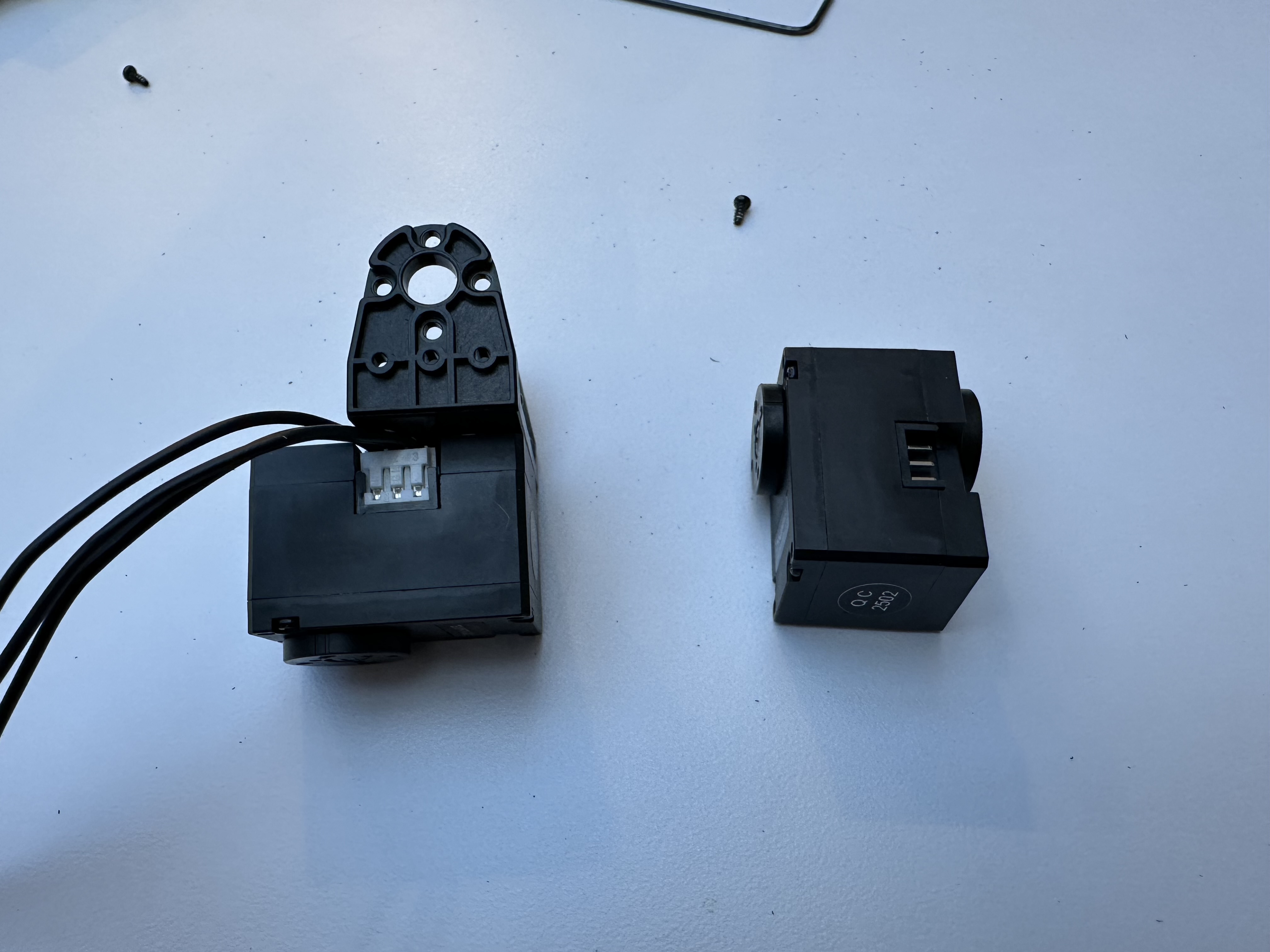
Shoulder Roll Joint#
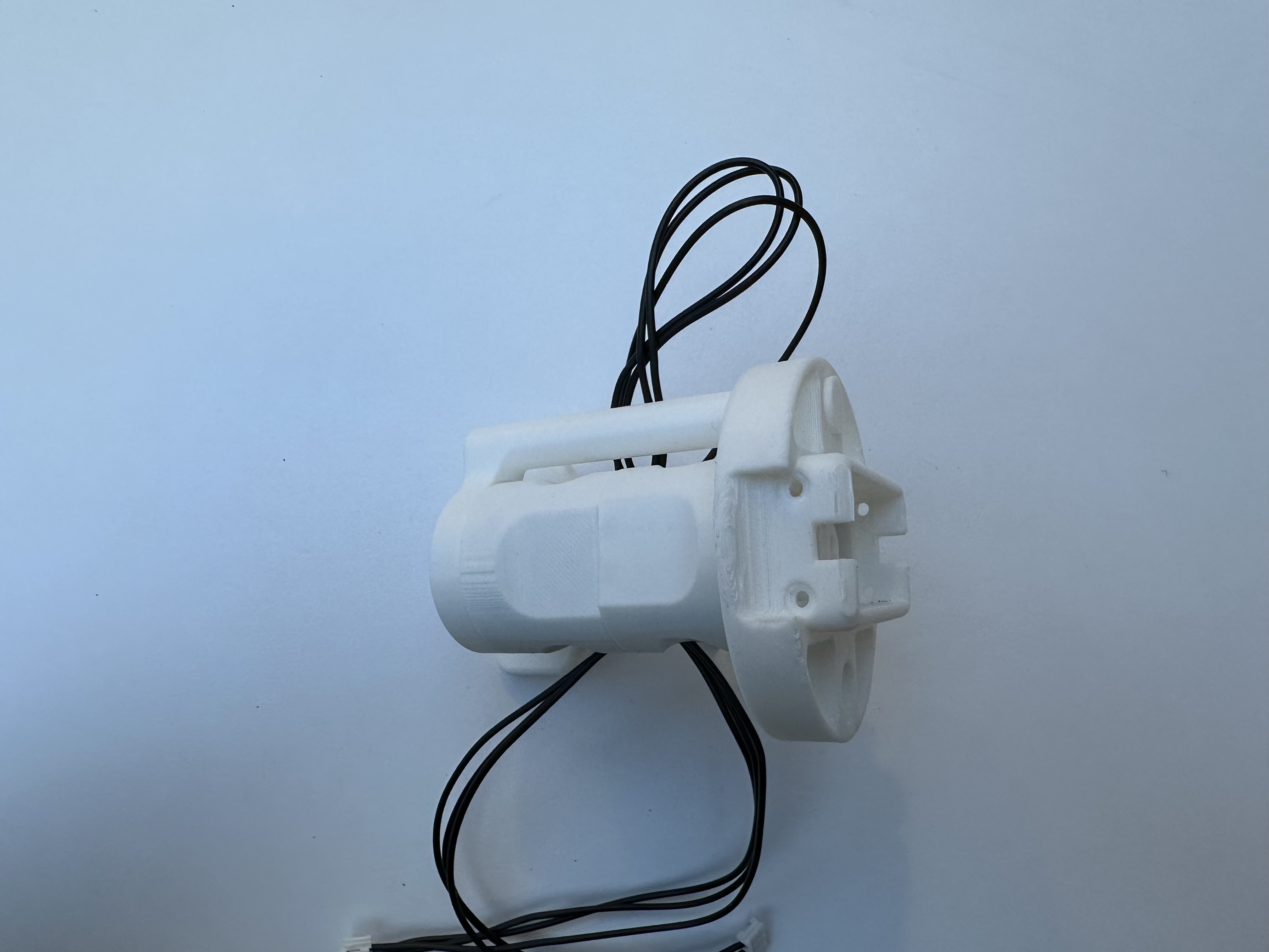
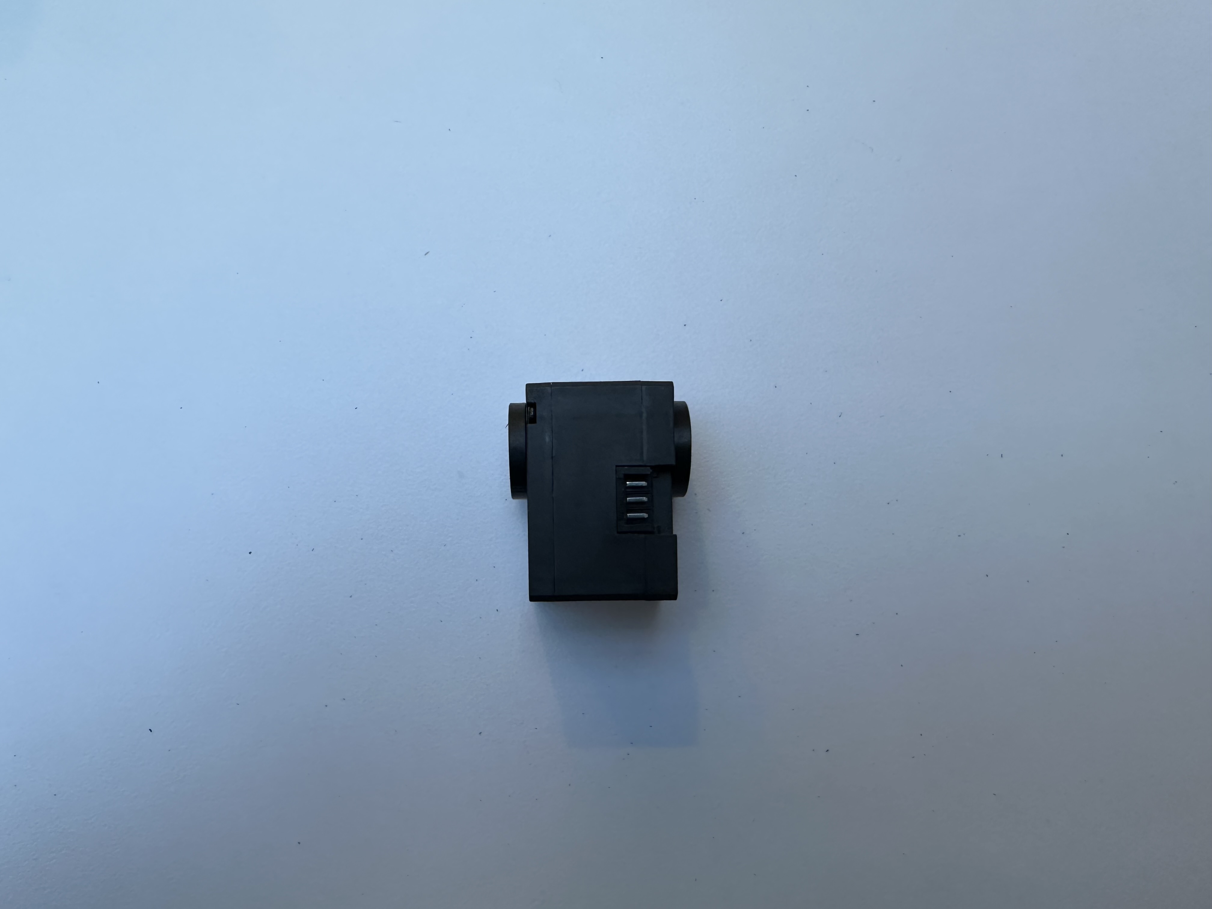
Take the shoulder rear mount mountback.obj and a Dynamixel motor.
First assign an ID 8 to the motor (we use IDs 0-7 for the left arm and IDs 8-15 for the right arm, although these can be changed).
Insert the motor into the mount.
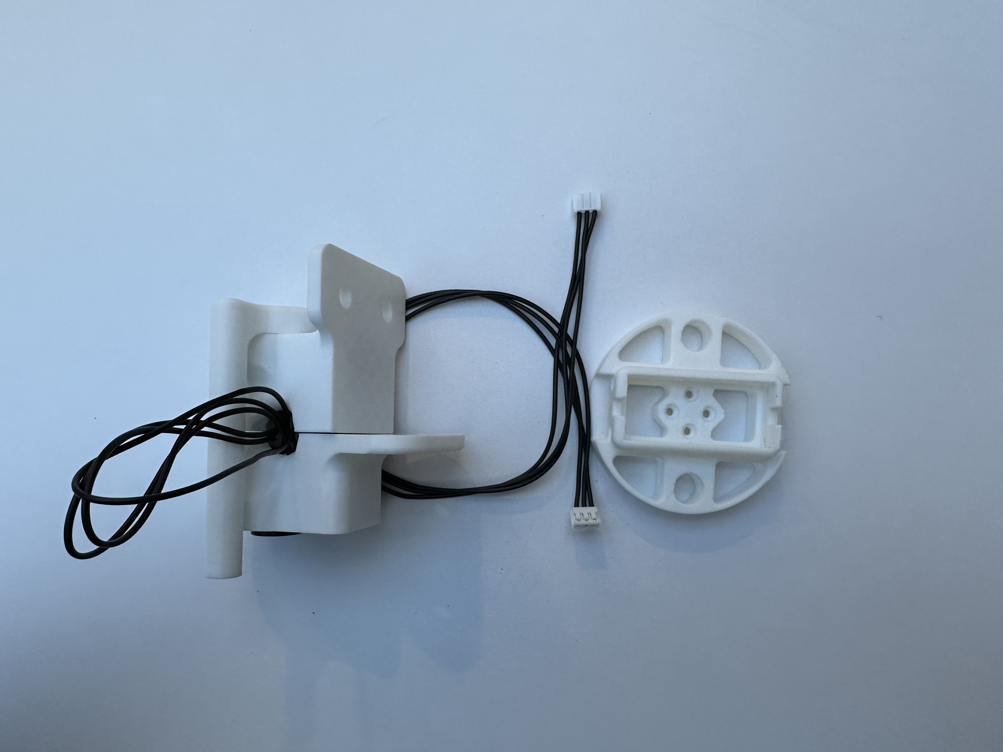
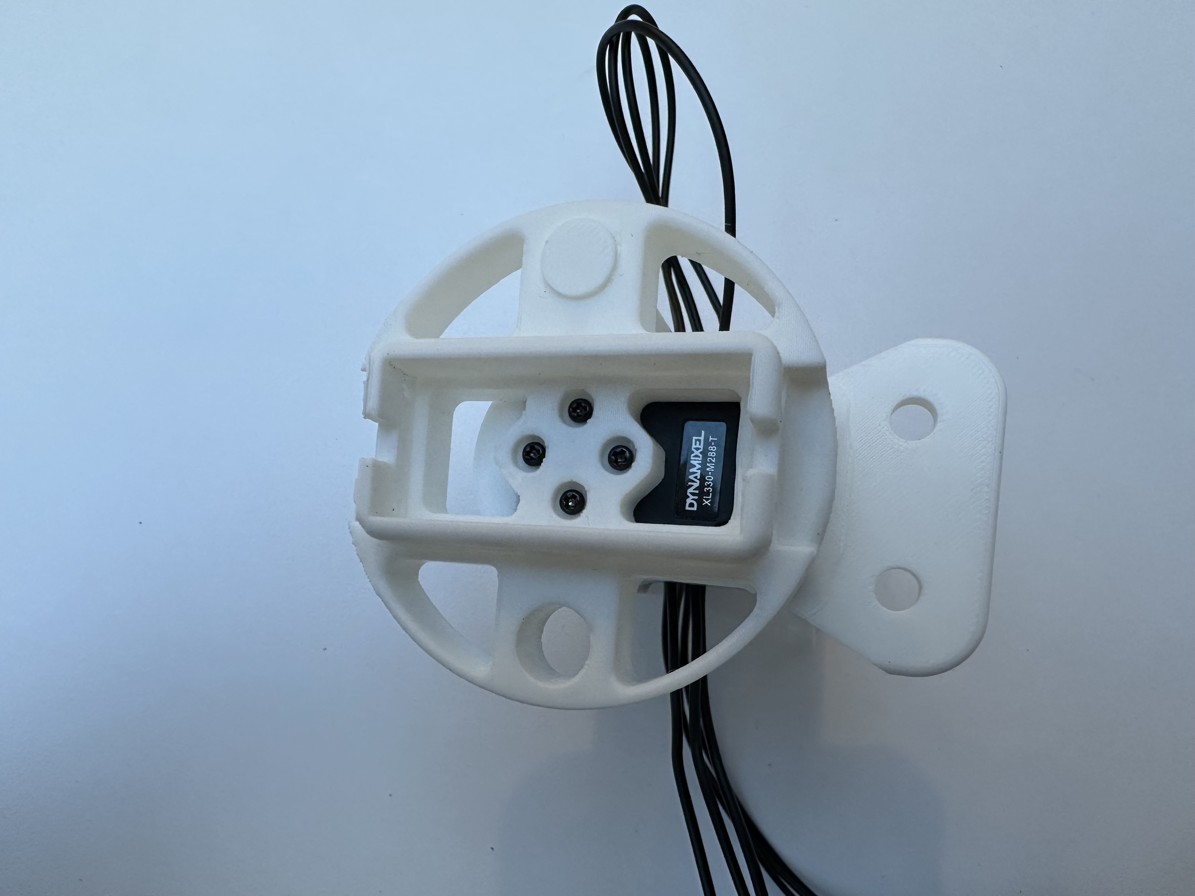
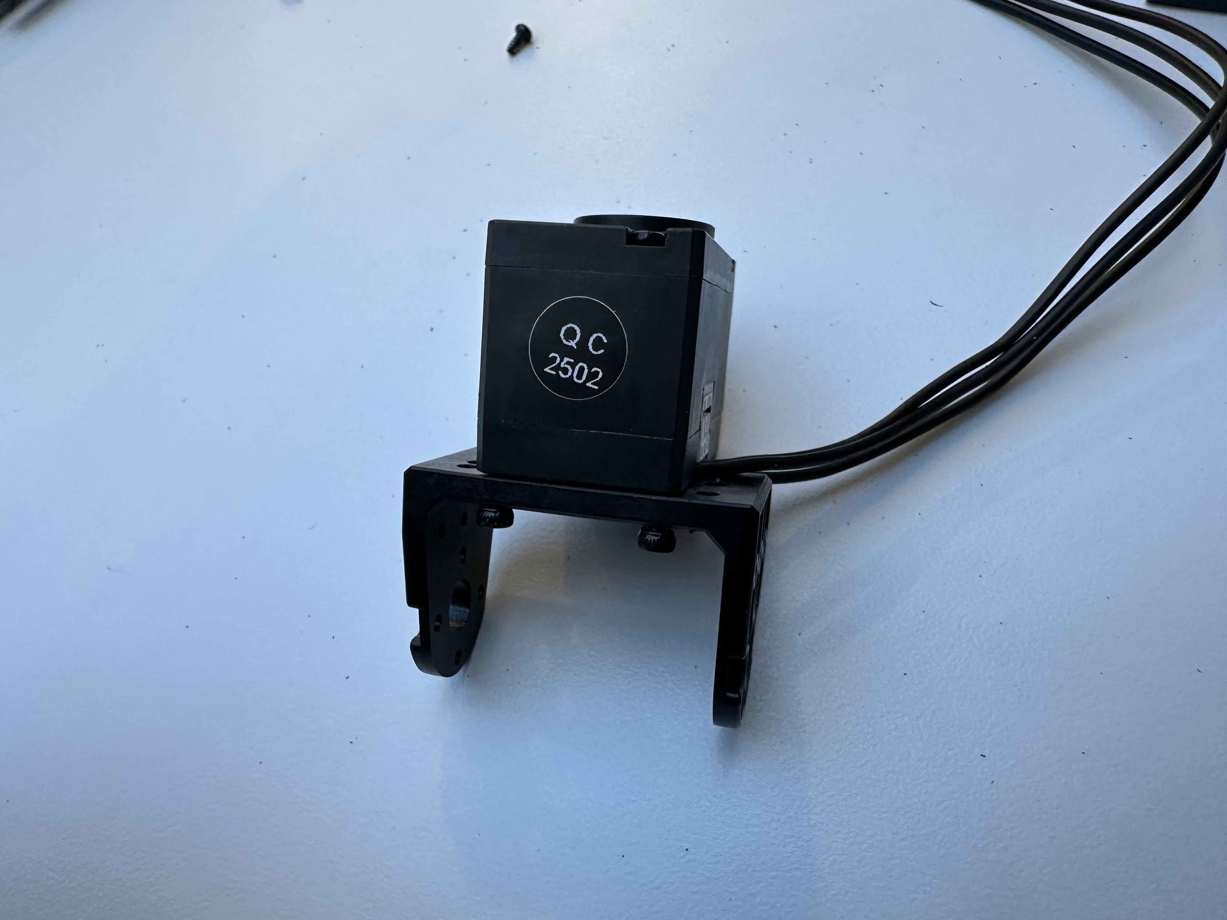
Take the shoulder mount mount.obj and a Dynamixel motor.
Assign an ID 9 to the motor. Insert the motor into the mount.
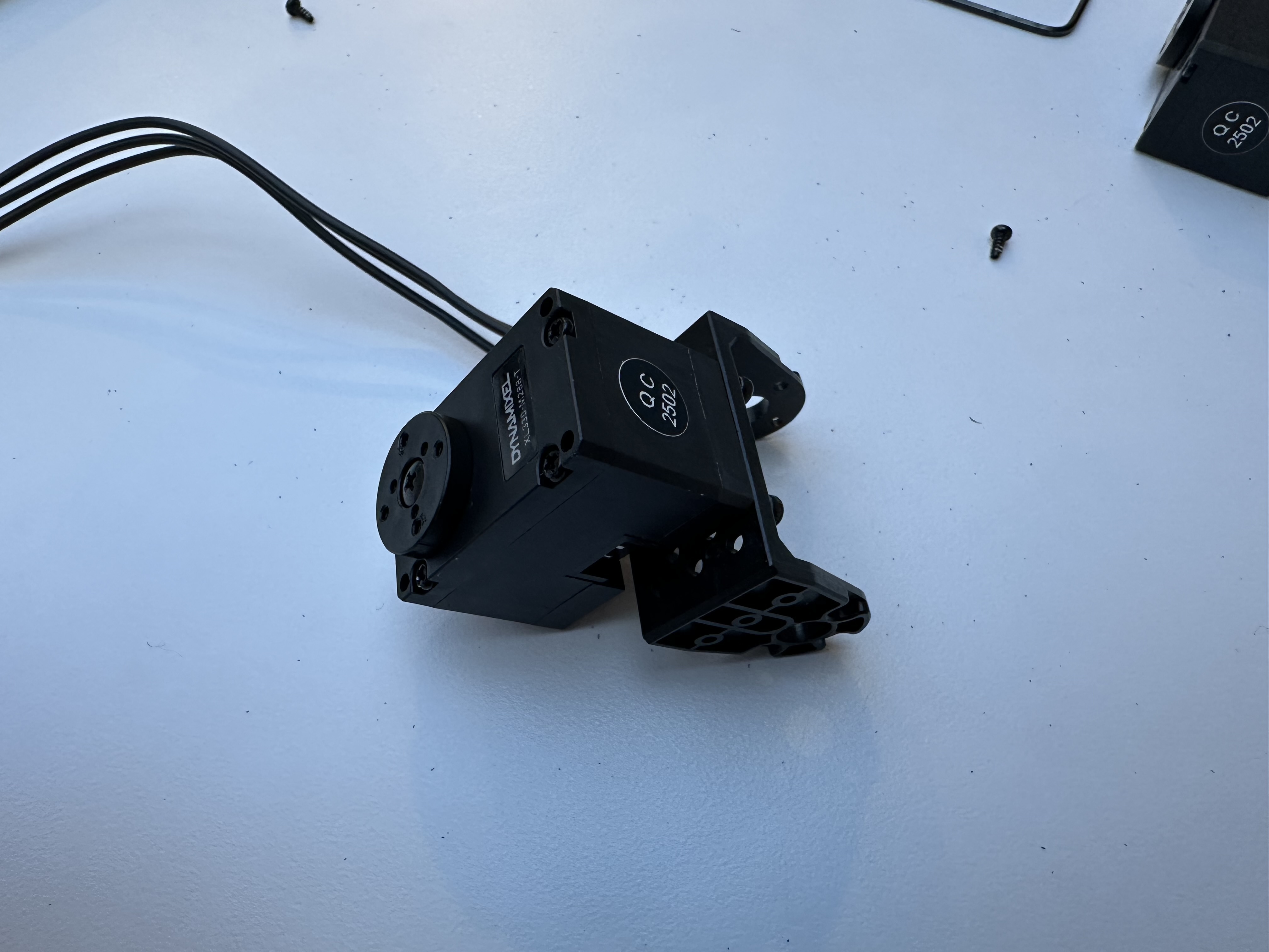
Take the shoulder coupling rod l2back.obj and the assembled shoulder rear mount.
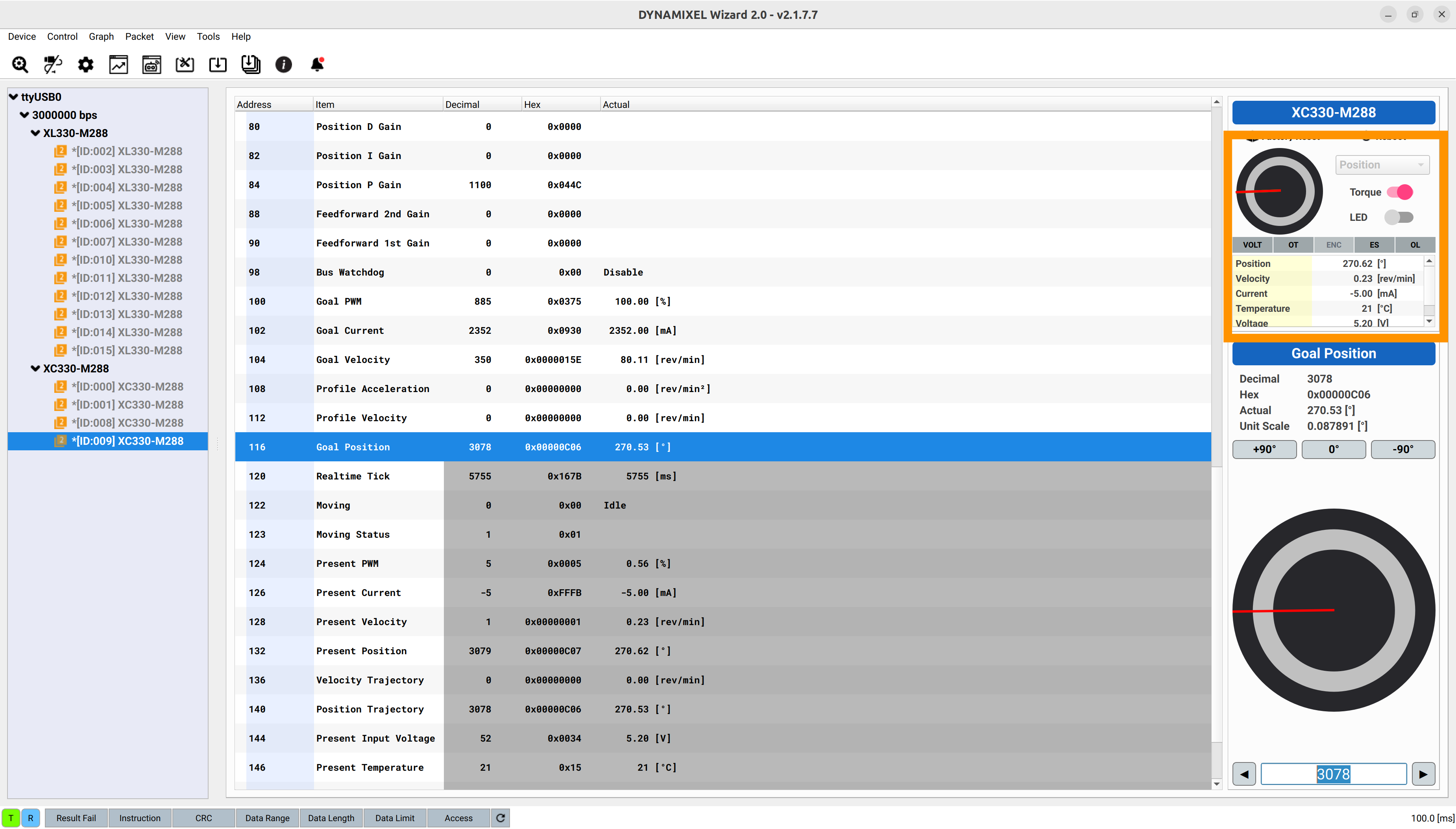
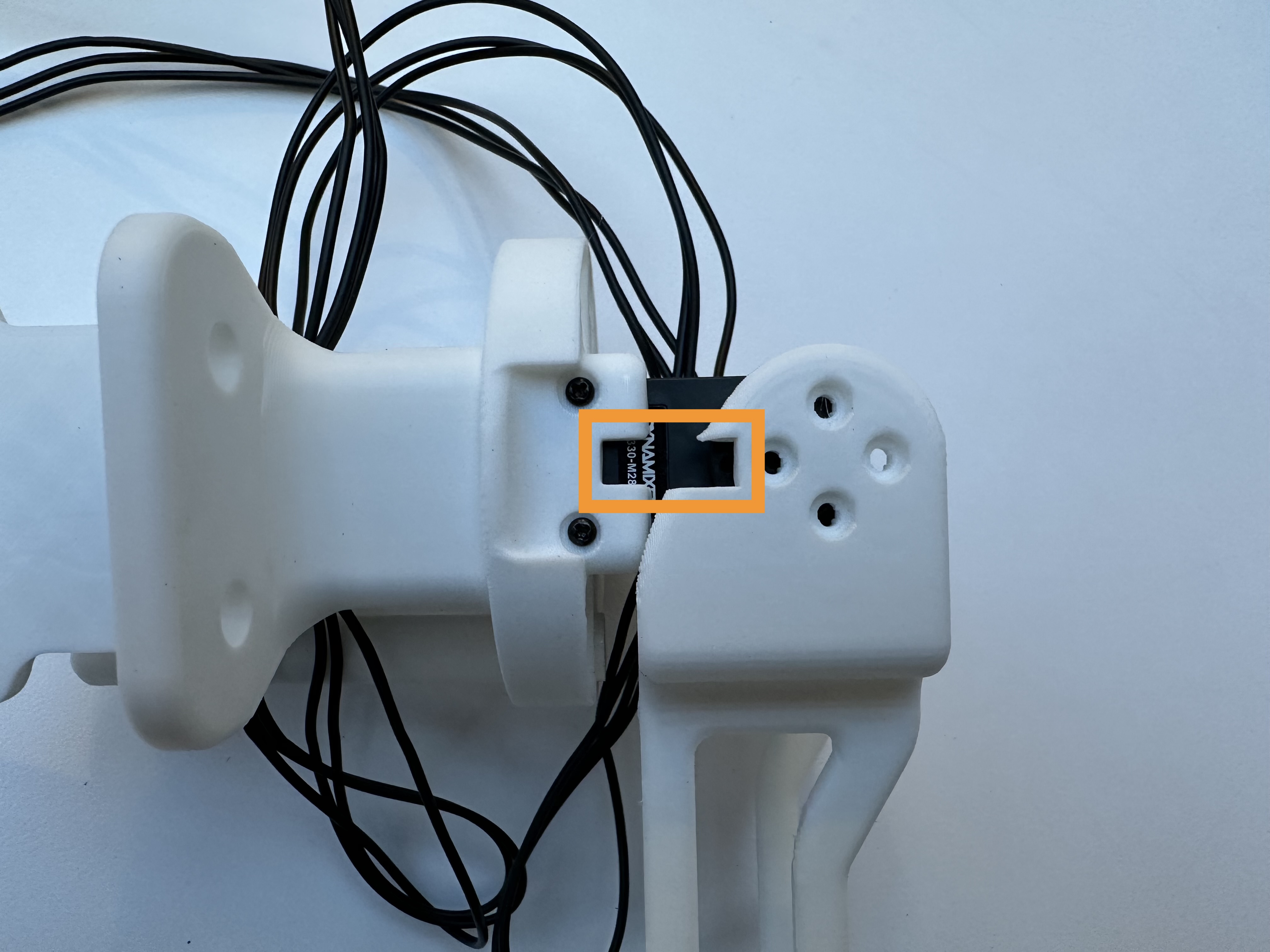
Screw the rod to the motor. Make sure to adjust the motor to the provided shaft position.
Note
Make sure the shaft position is at 270 degrees when the arm is at the following configuration.
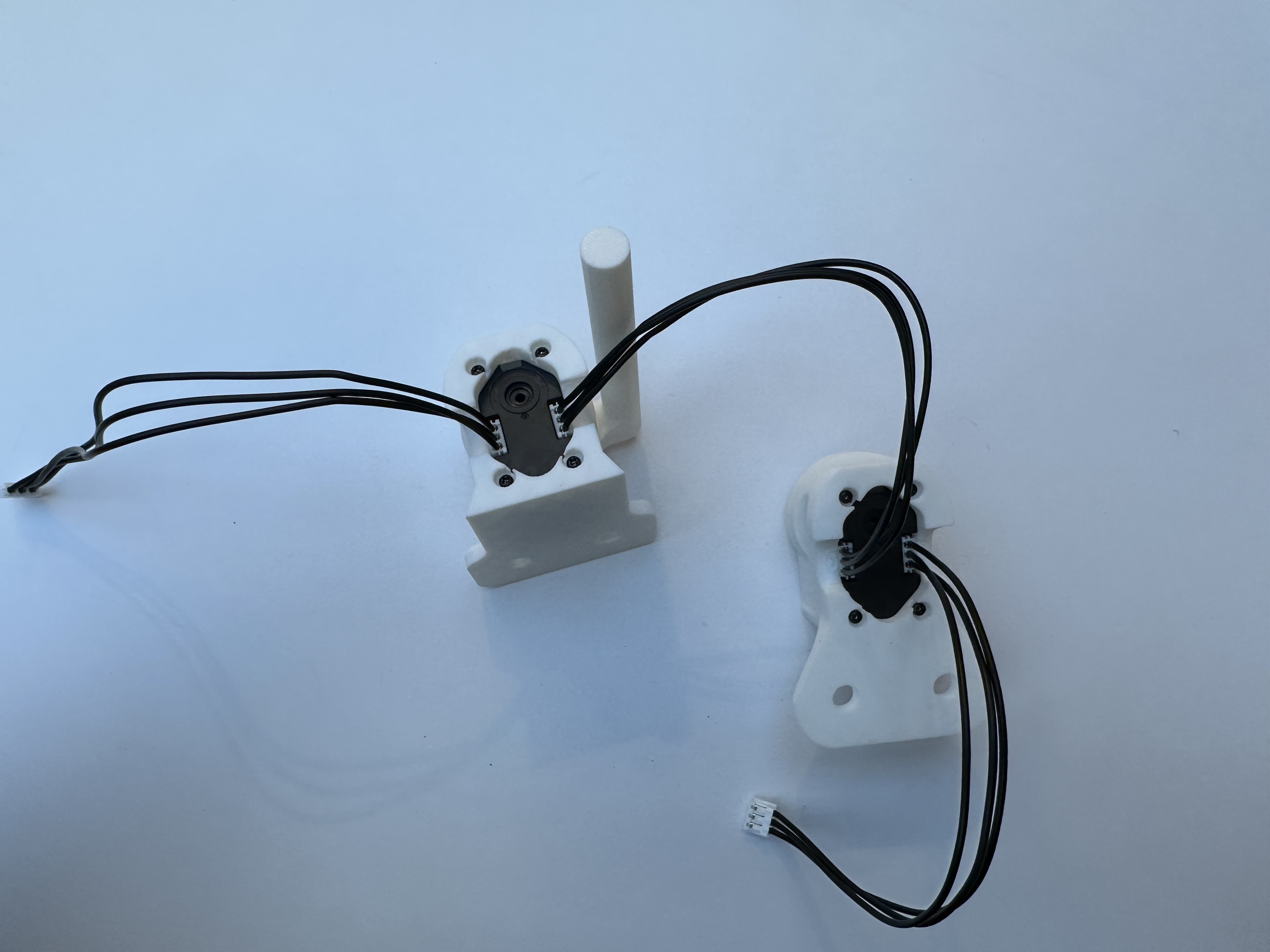
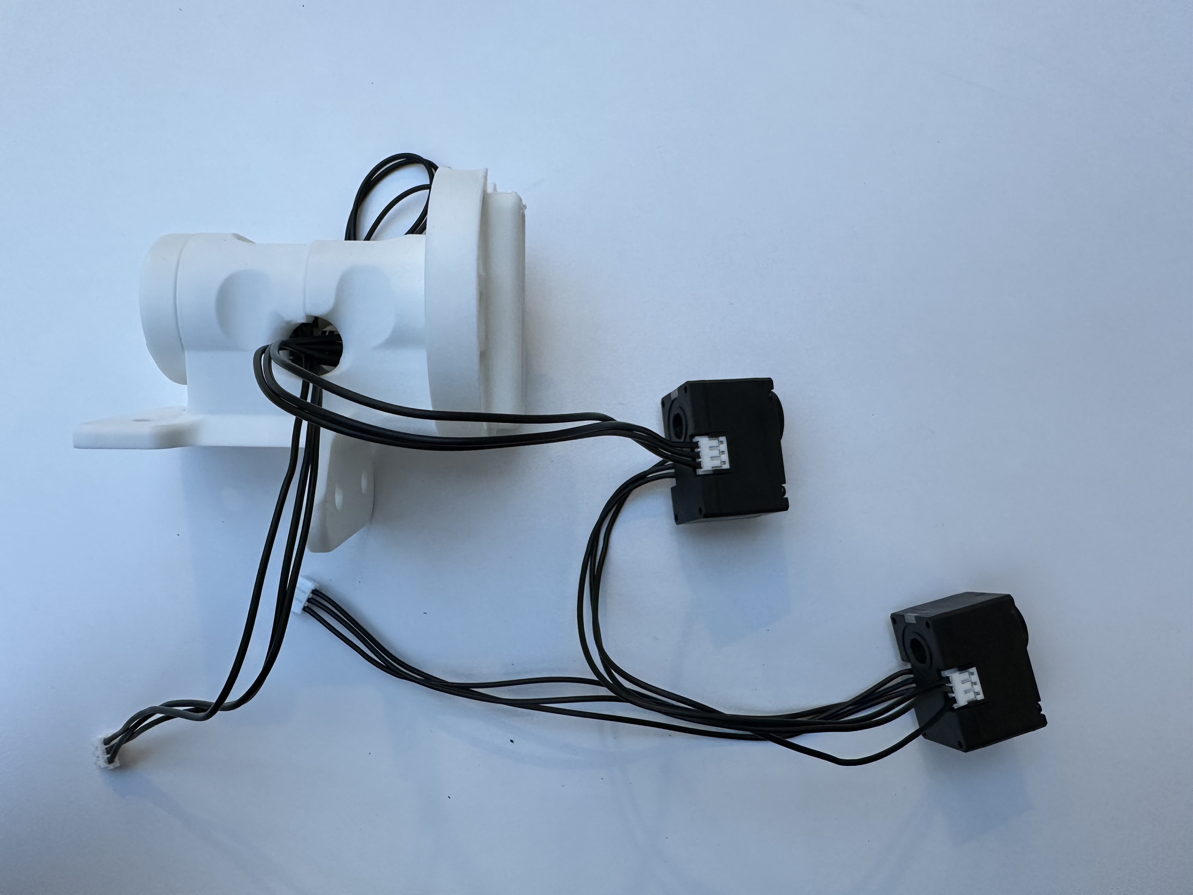
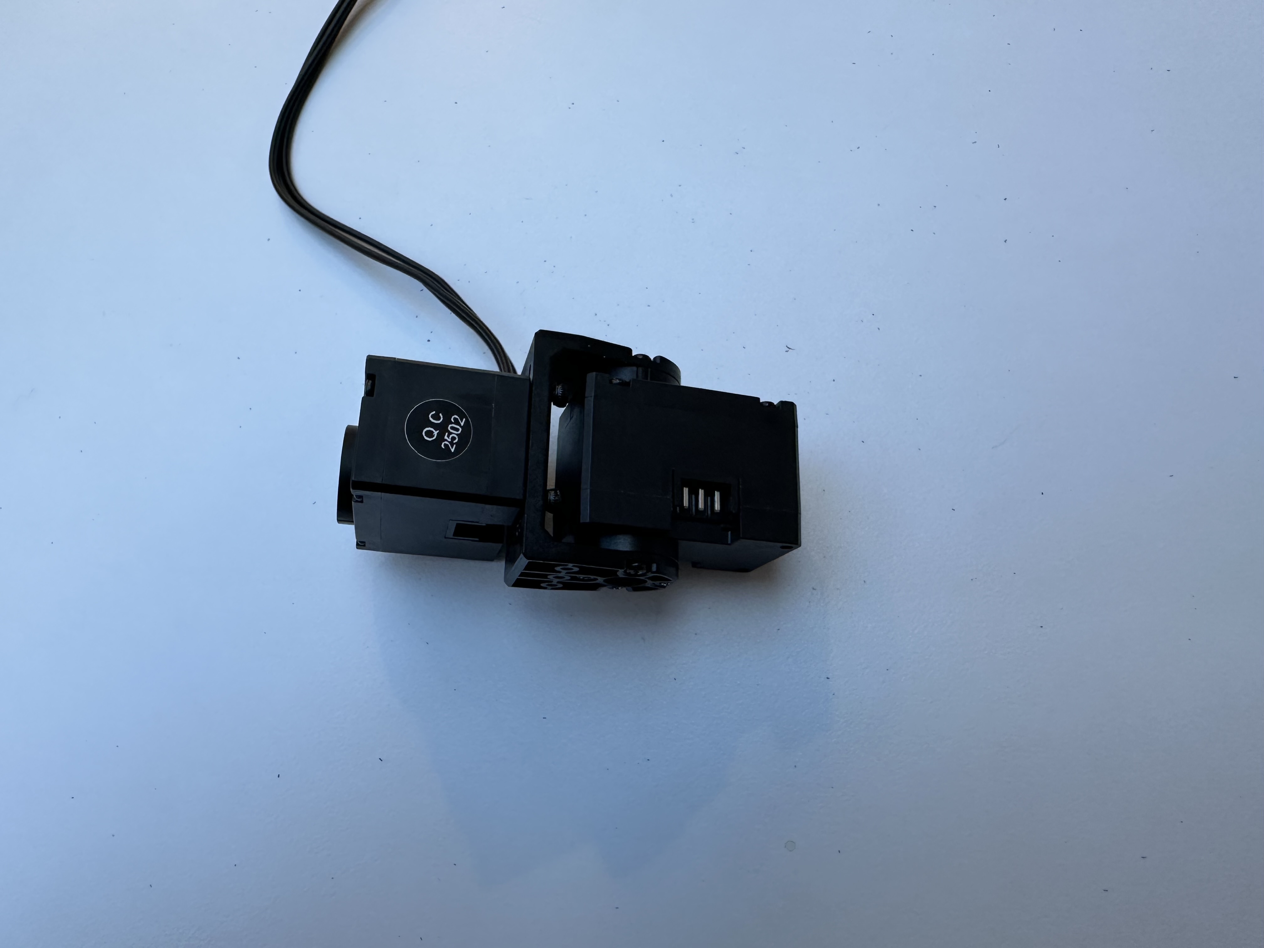
Connect the assembled shoulder rear motor and the shoulder motor with cables.
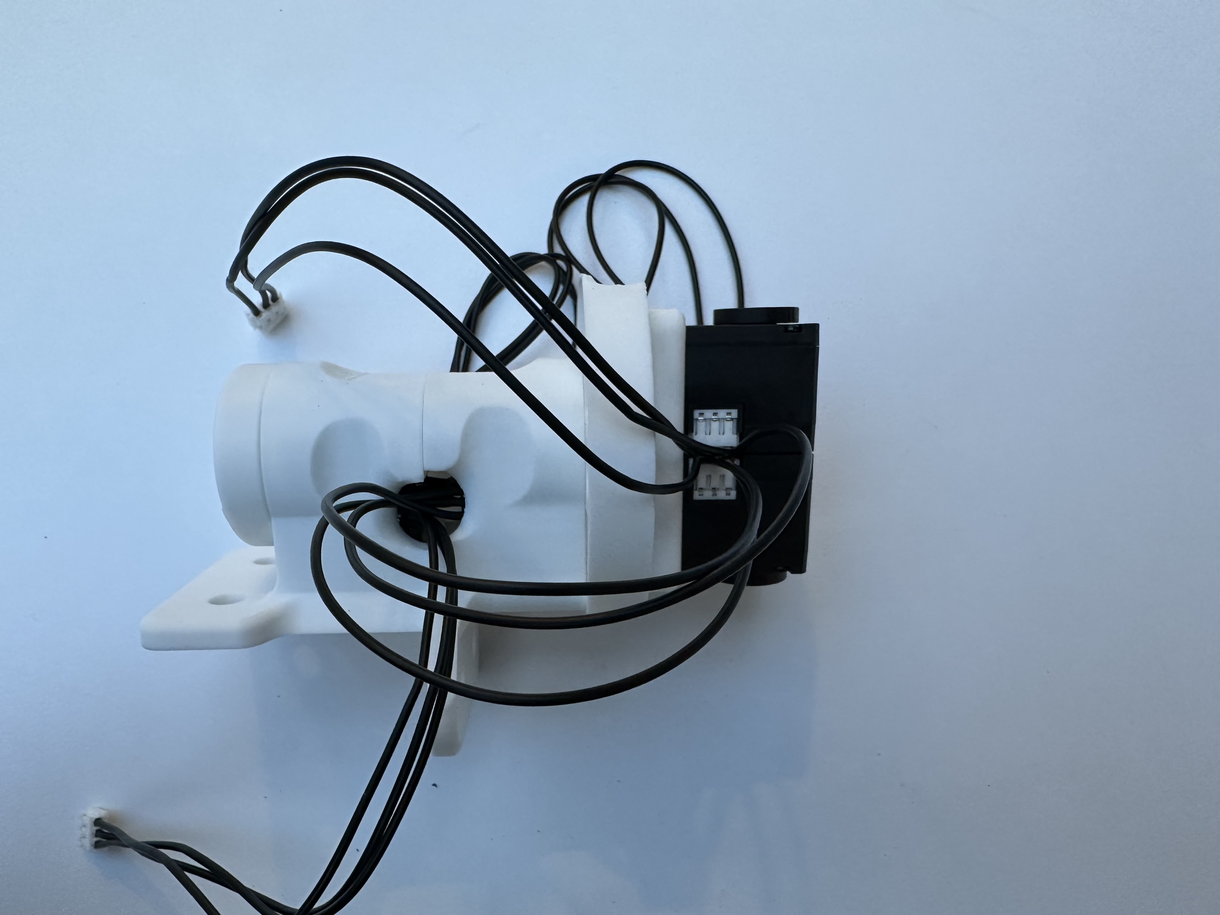
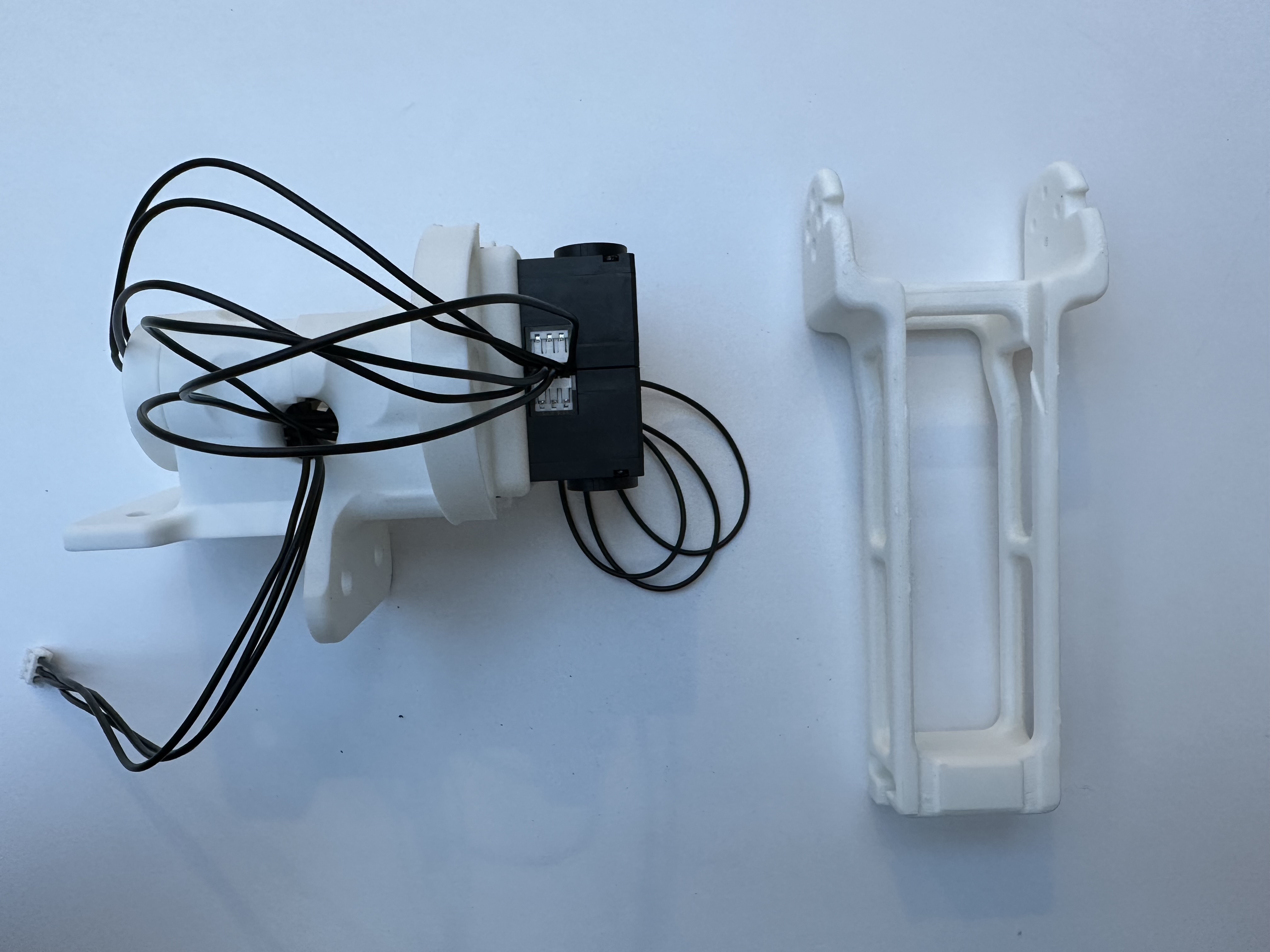
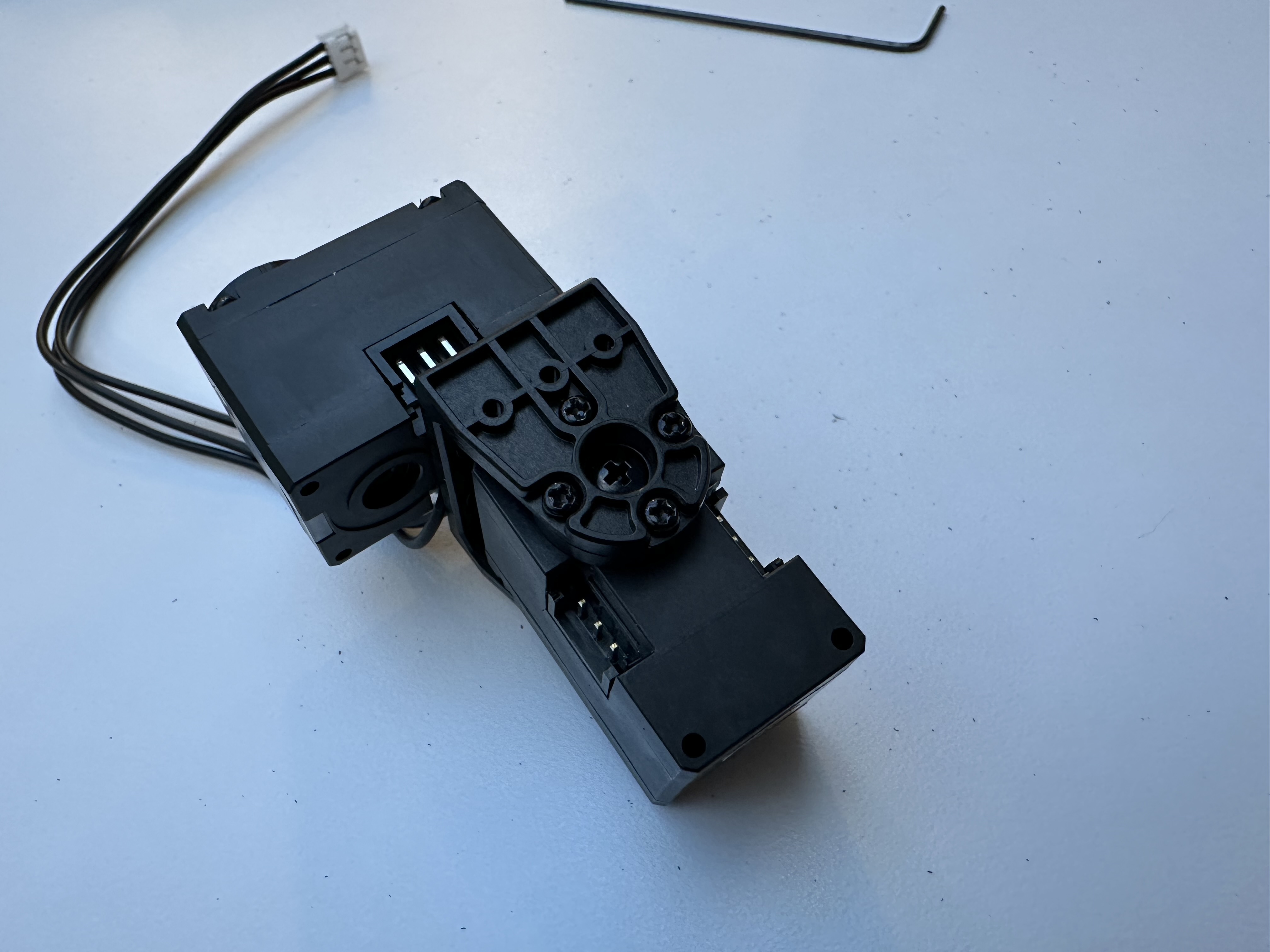
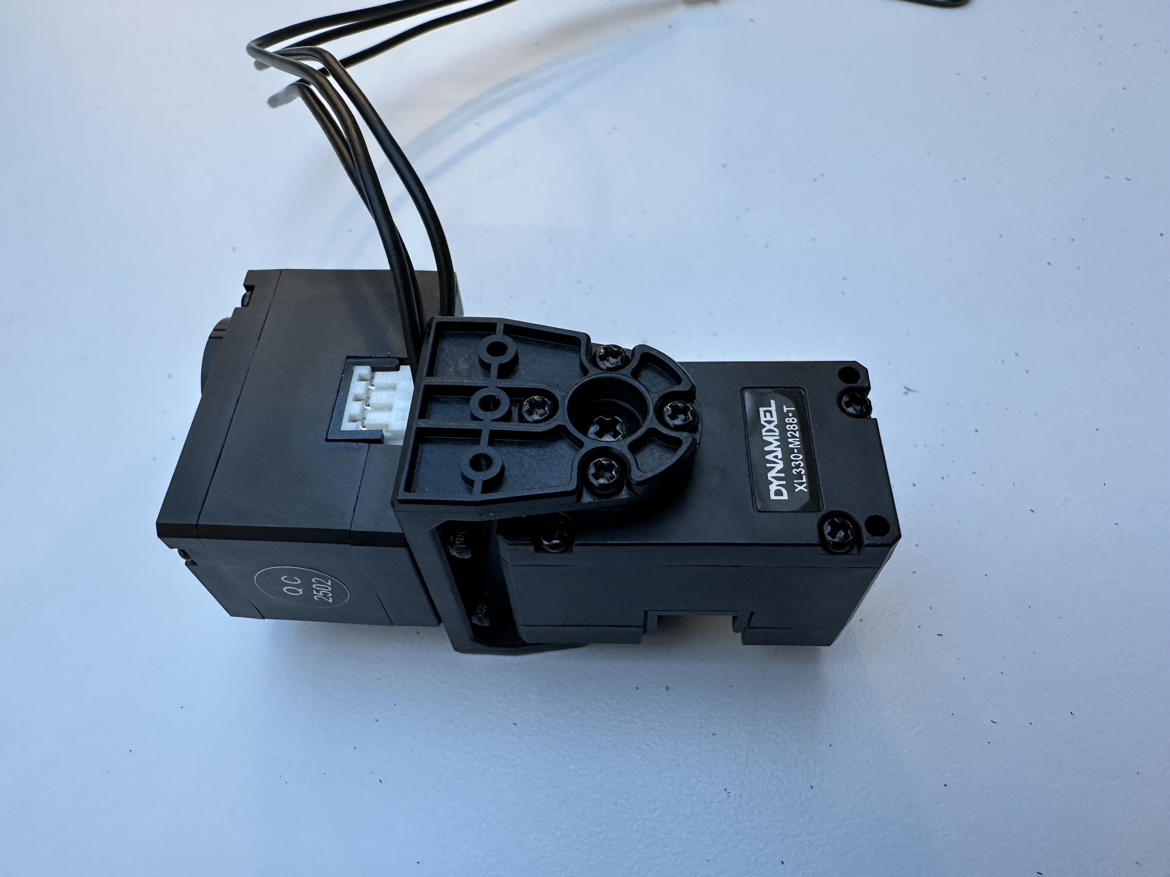
Put the shoulder mount and rear mount back to back. And take the shoulder roll link l2.obj.
Insert the roll link to the rod and motor shaft. Make sure to adjust the motor to the provided shaft position.
Note
Make sure the shaft position is at 270 degrees when the arm is at the following configuration.
Tighten the screws to secure the link.
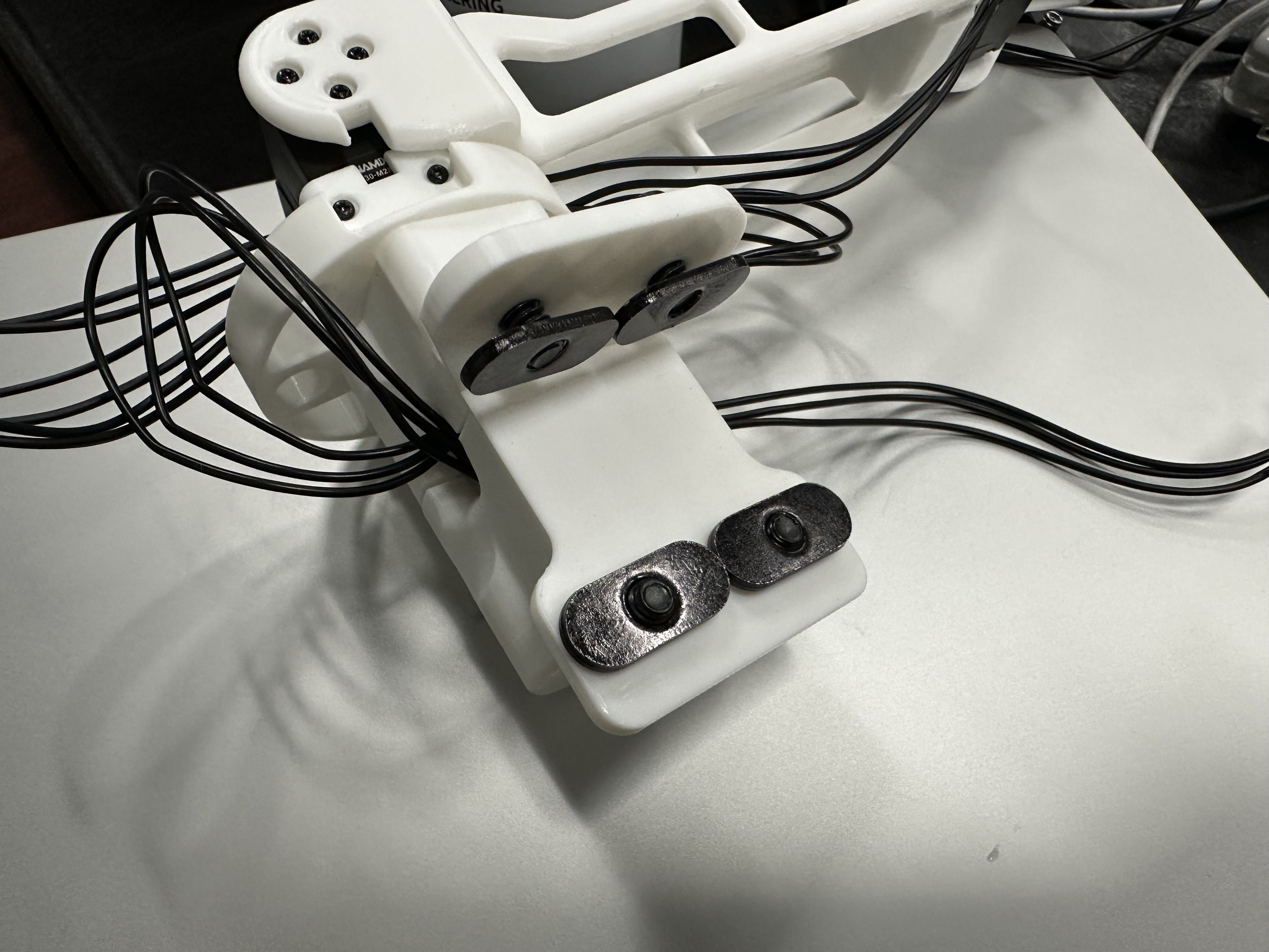
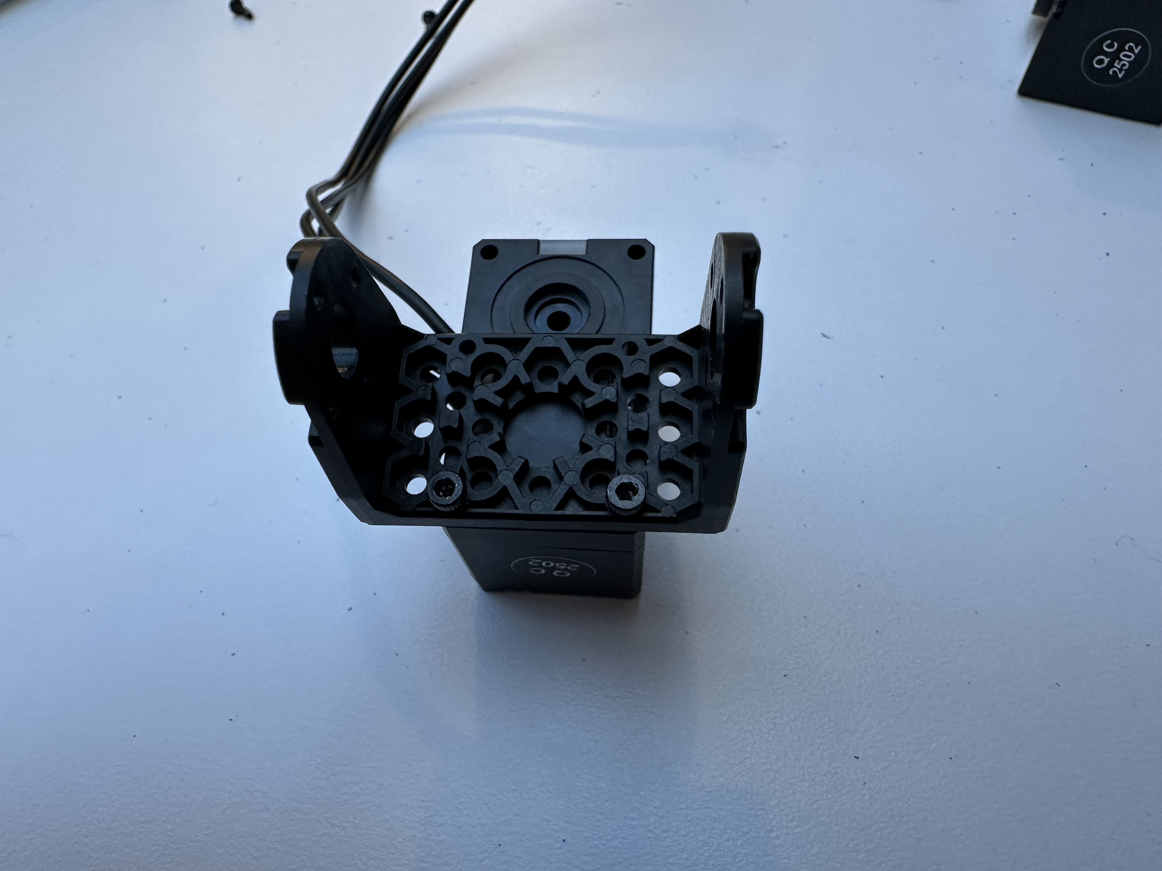
Upper Arm Joint#
Now assemble the upper arm joint. Take two Dynamixel motors, assign IDs 10 and 11 to them, and connect them with cables.
Put the two motors back to back, and insert them into the slot of the shoulder roll link.
Take the upper arm l3.obj. Align the two slots as shown below.
Make sure to adjust motors to the provided shaft positions.
Note
Make sure the shaft positions are at 90 degrees when the arm is at the following configuration.

Tighten the screws to secure the upper arm. Make sure the cable is routed properly.
Elbow Joint#
First assemble a Dynamixel motor with an idler. Assign an ID 12 to the motor.
Insert the motor to the assembled upper arm, tighten the screws, and connect the motor with cables.
Take the elbow l4.obj and insert a new Dynamixel motor into it. Tighten the screws and connect the motor with cables.
Assign an ID 13 to the motor.
Align the elbow with the upper arm, make sure slots are aligned and the elbow facing outwards as shown below.
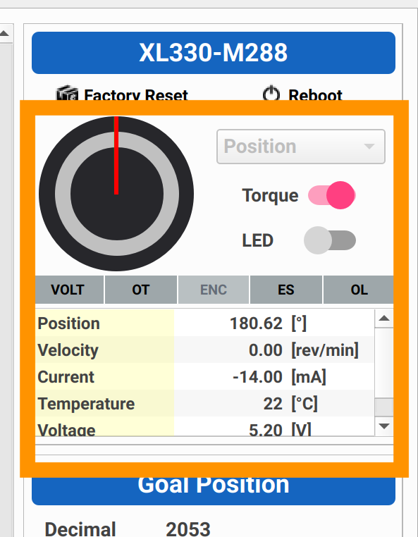
Adjust the elbow motor to the provided shaft position.
Note
Make sure the shaft position is at 180 degrees when the arm is at the following configuration.

Tighten the screws to secure the elbow and connect the motor with cables.
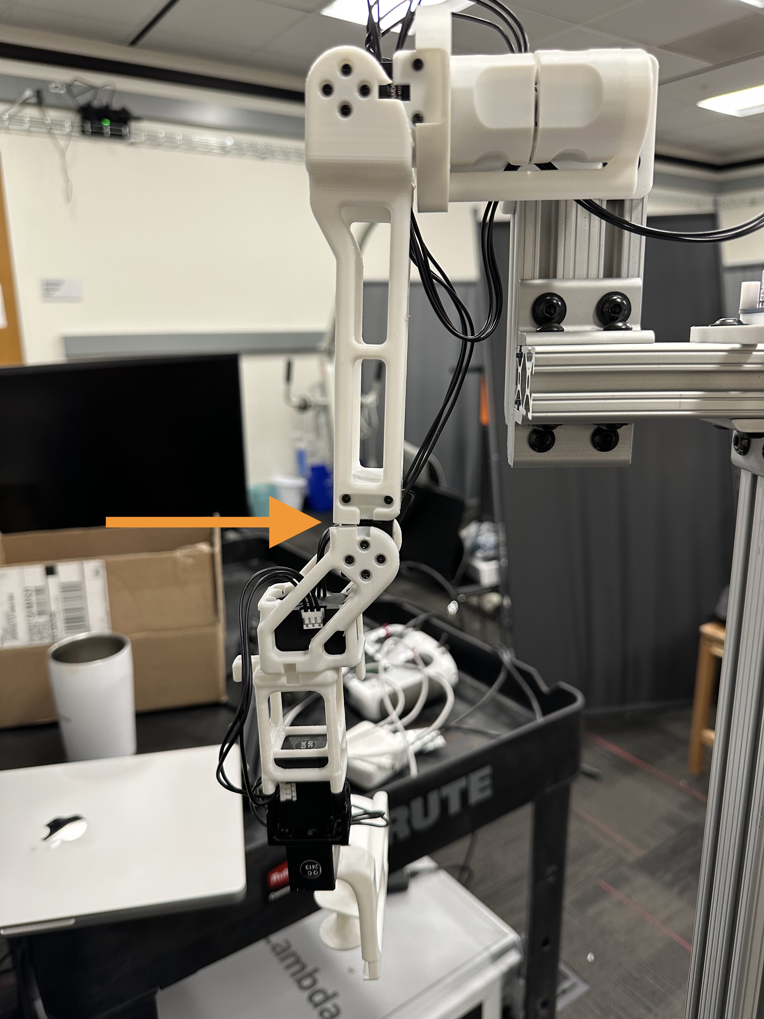
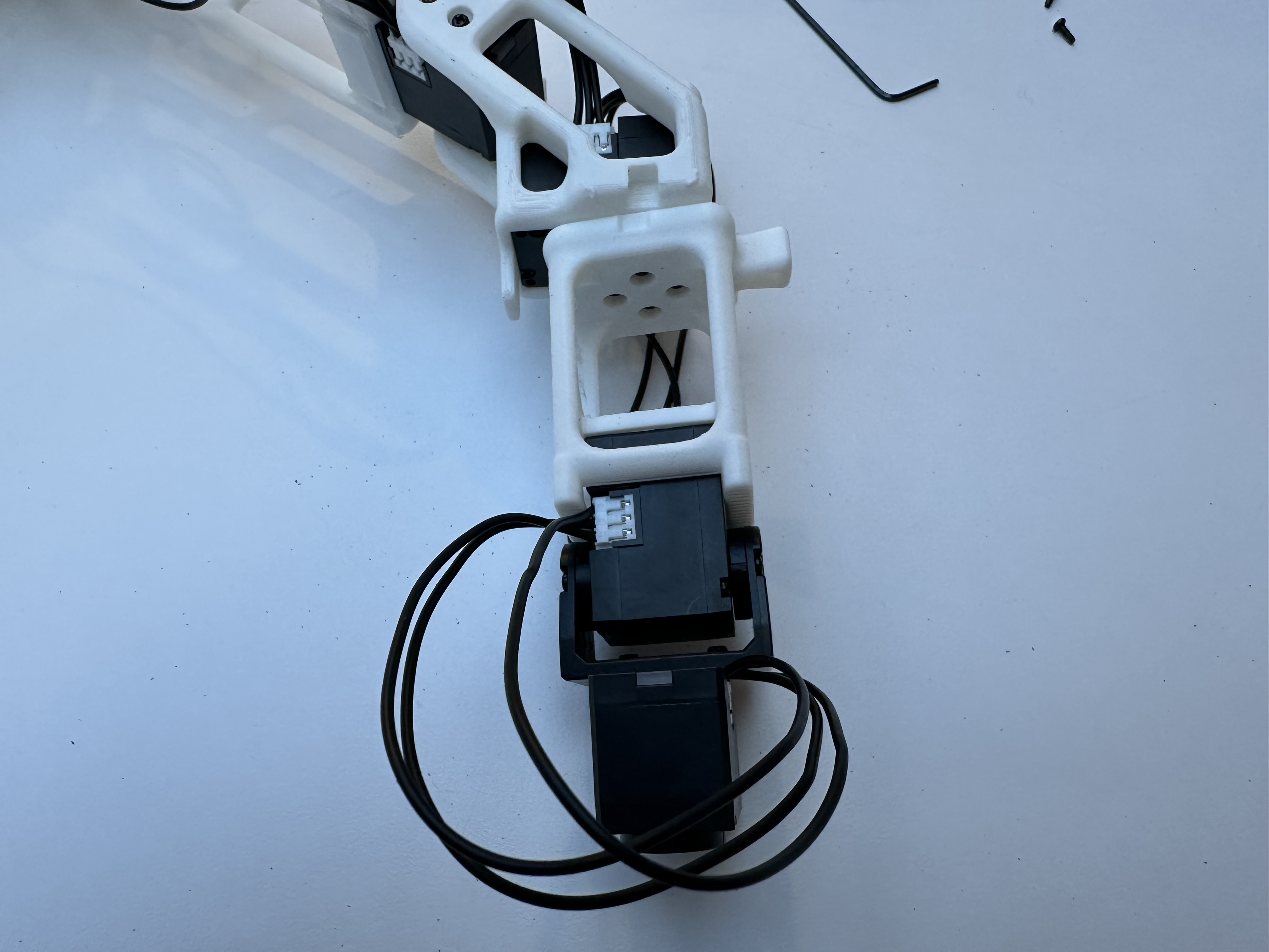
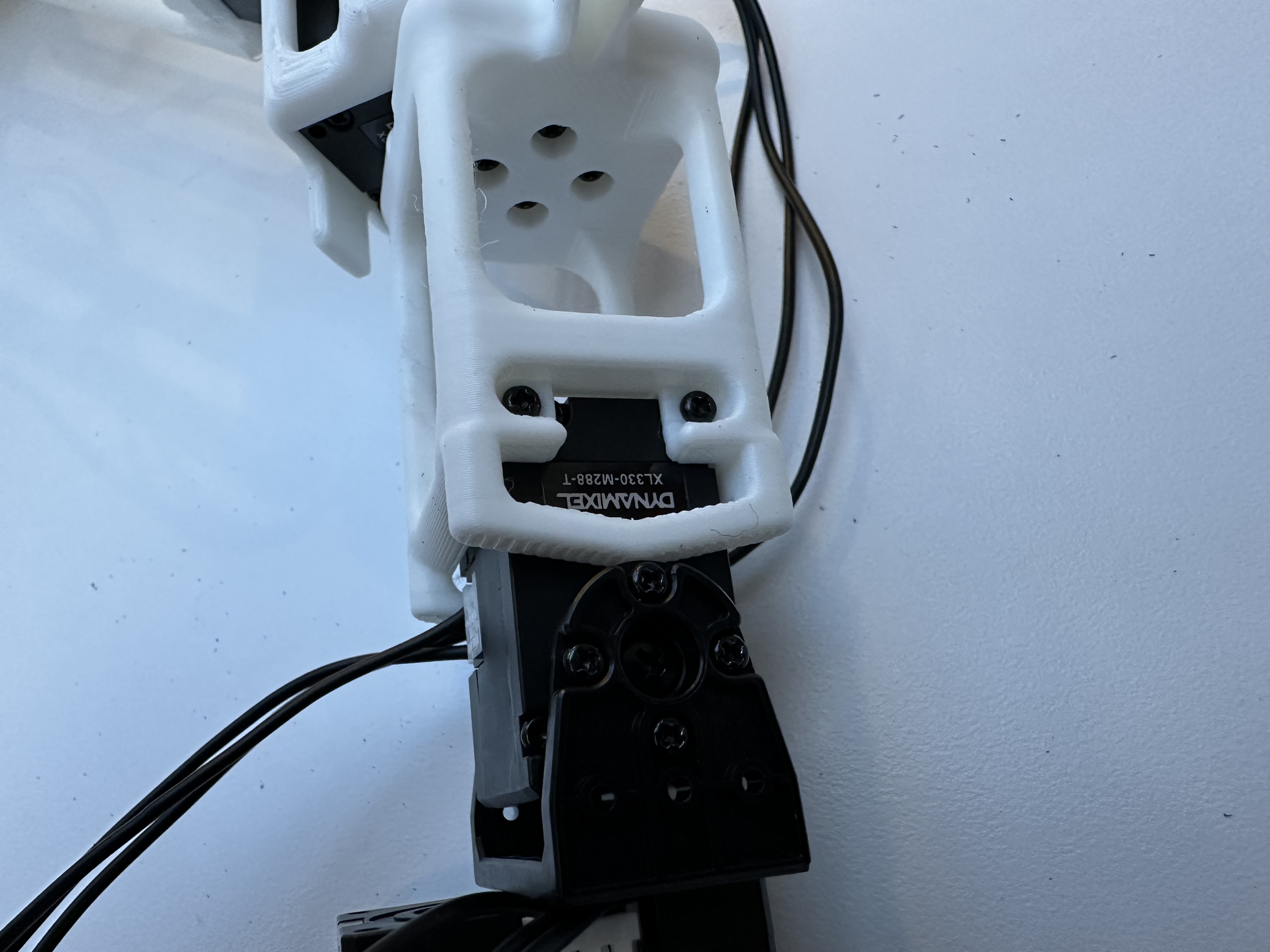
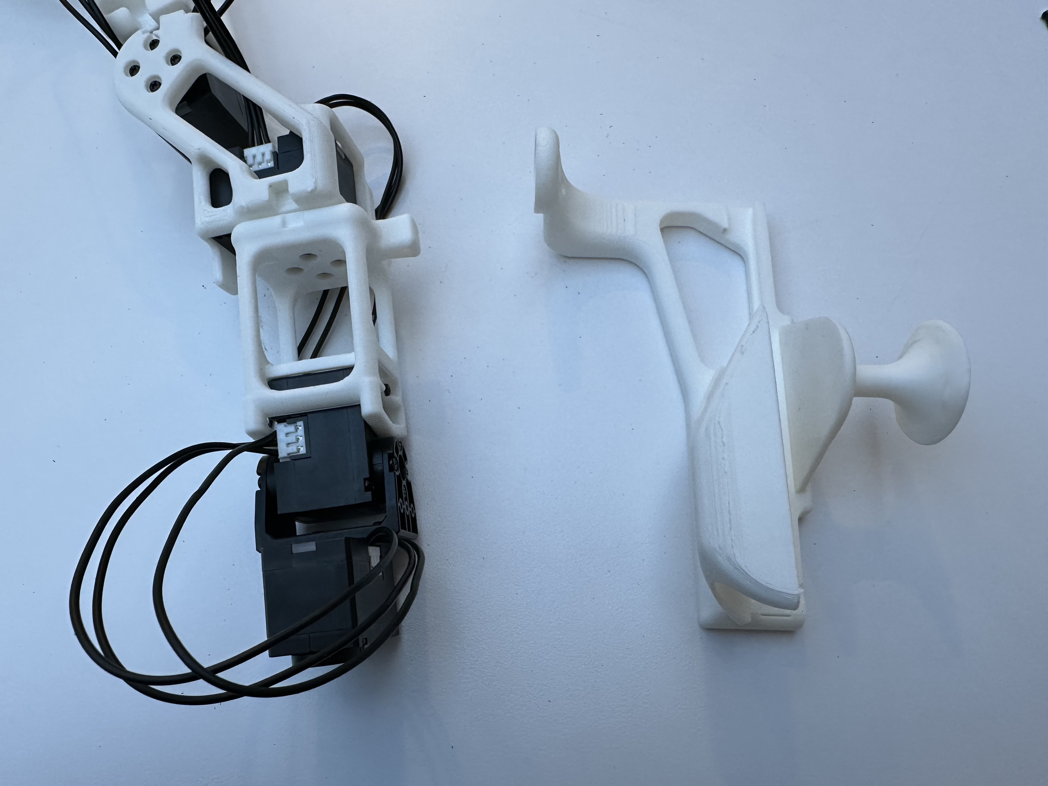
Forearm Joint#
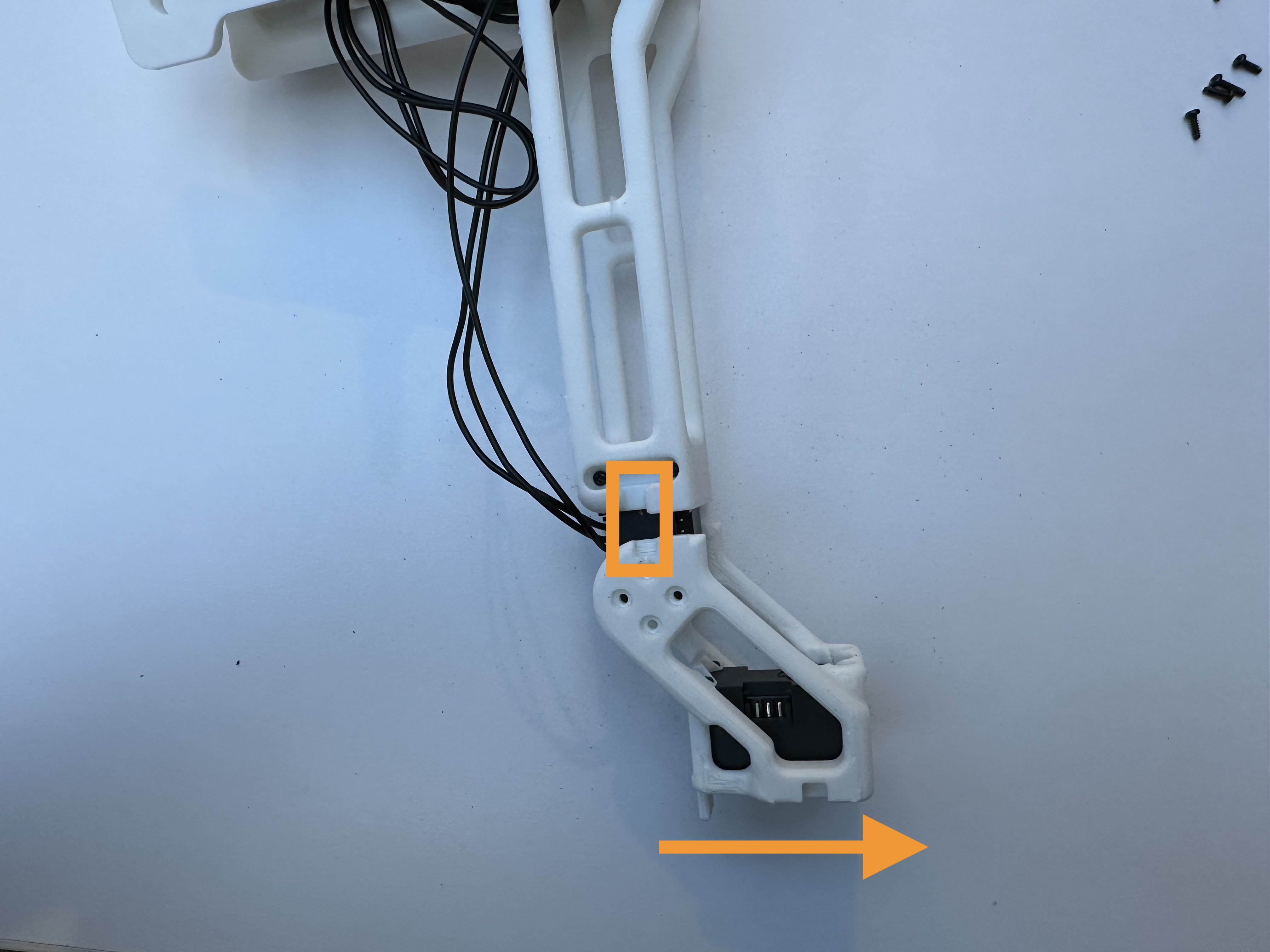
Take the forearm l5.obj.
Align the forearm with the assembled elbow, make sure slots are aligned and the stop block facing outwards as shown below. Ensure the forearm motor is adjusted to the provided shaft position.
Note
Make sure the shaft position is at 180 degrees when the arm is at the following configuration.
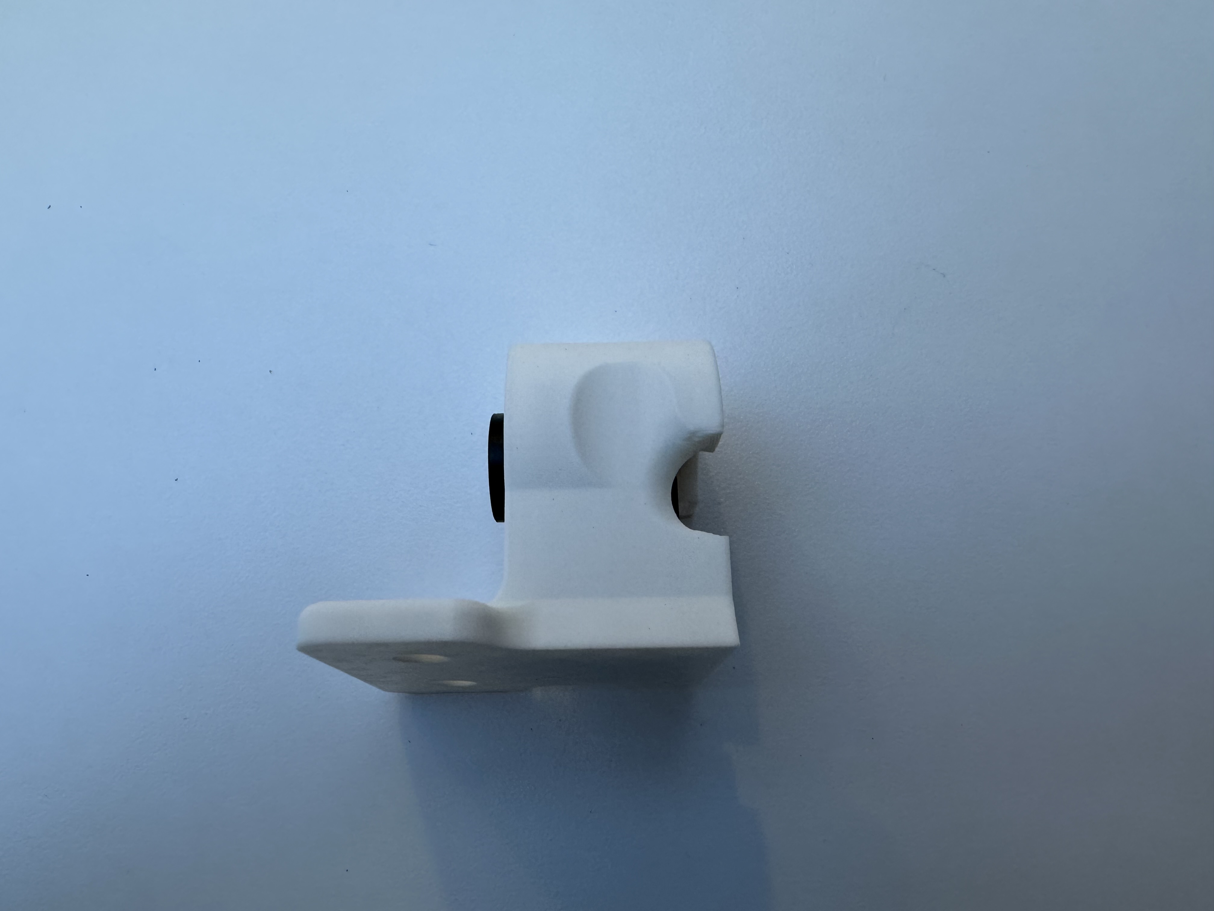
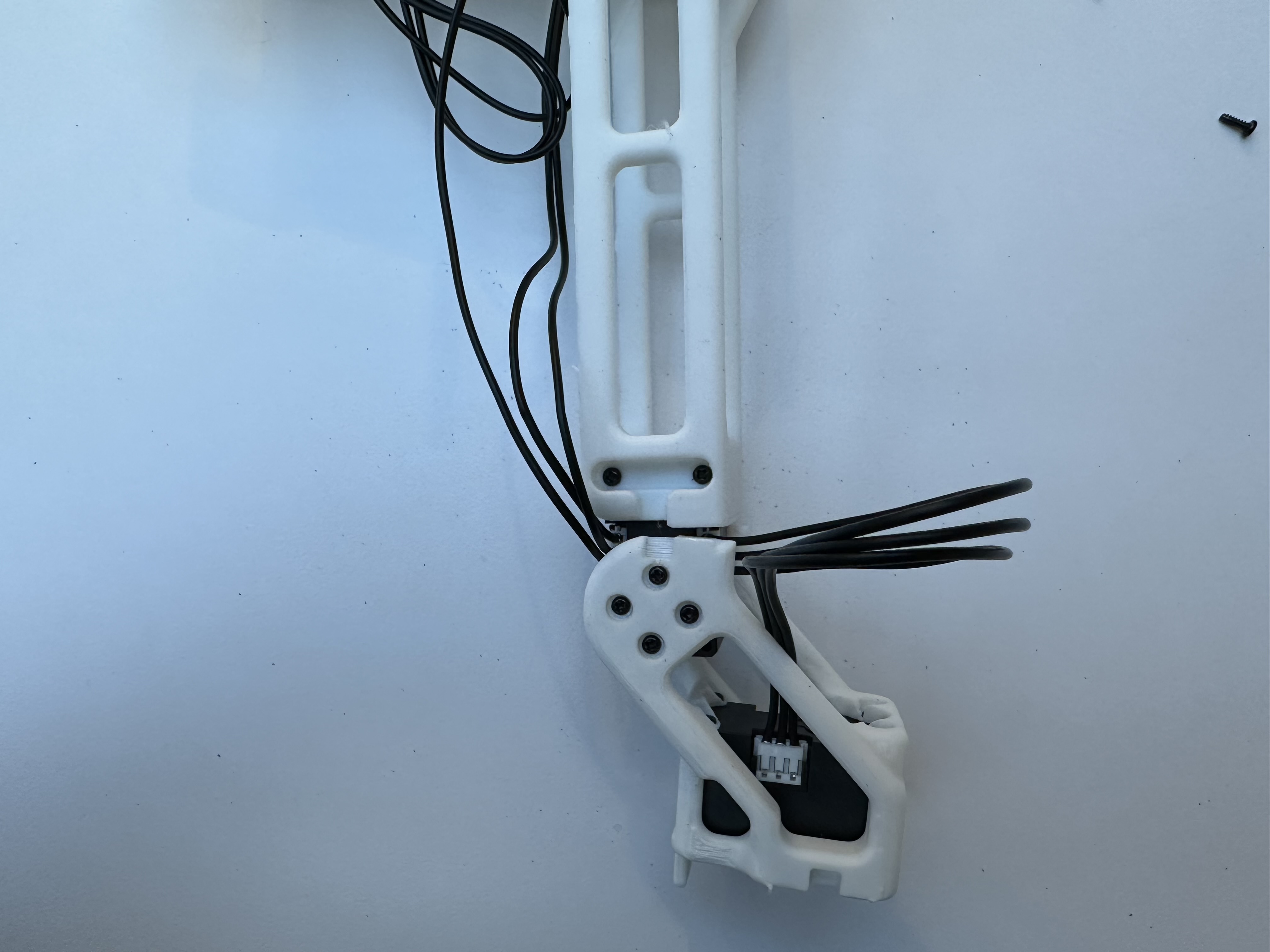
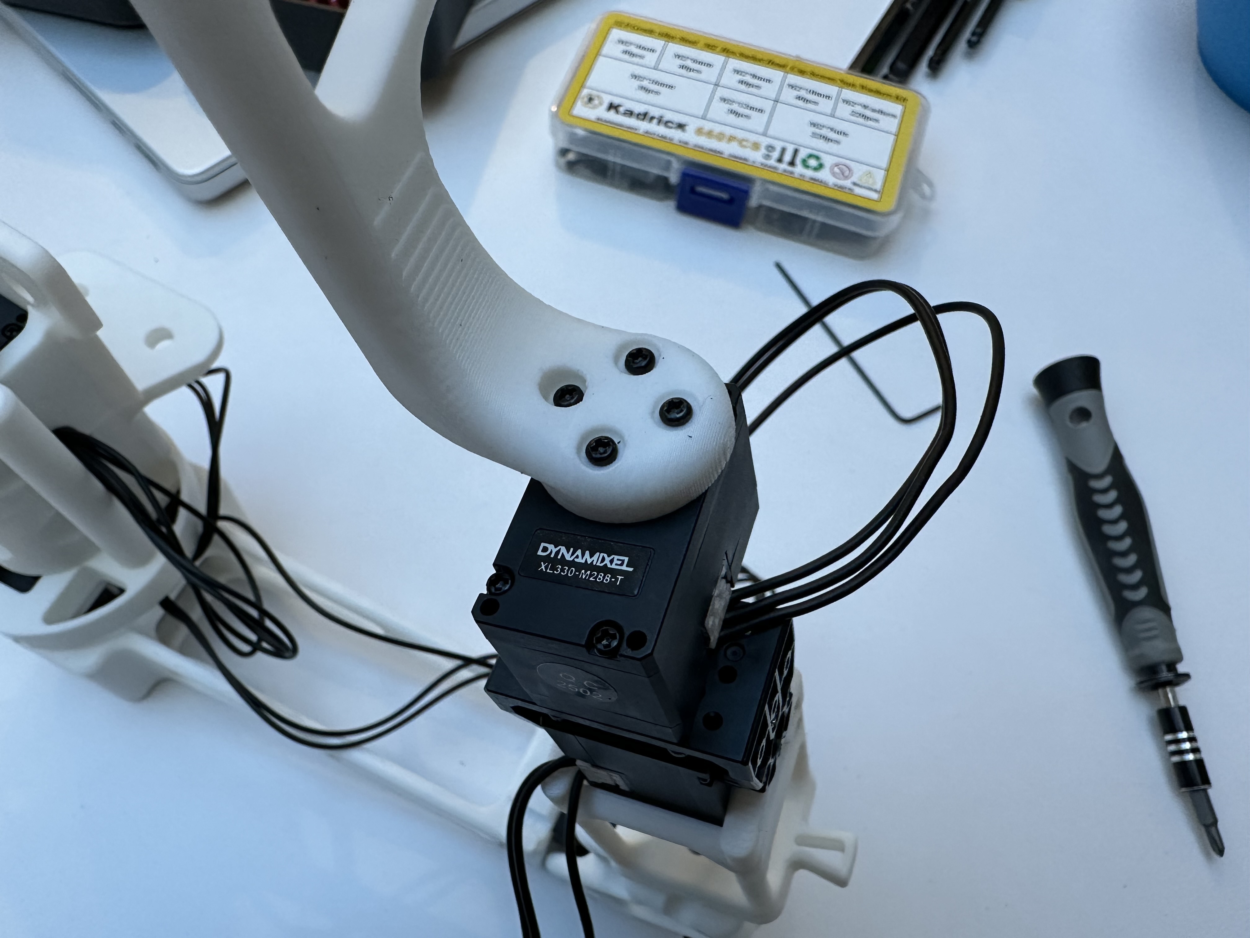
Wrist Joint#
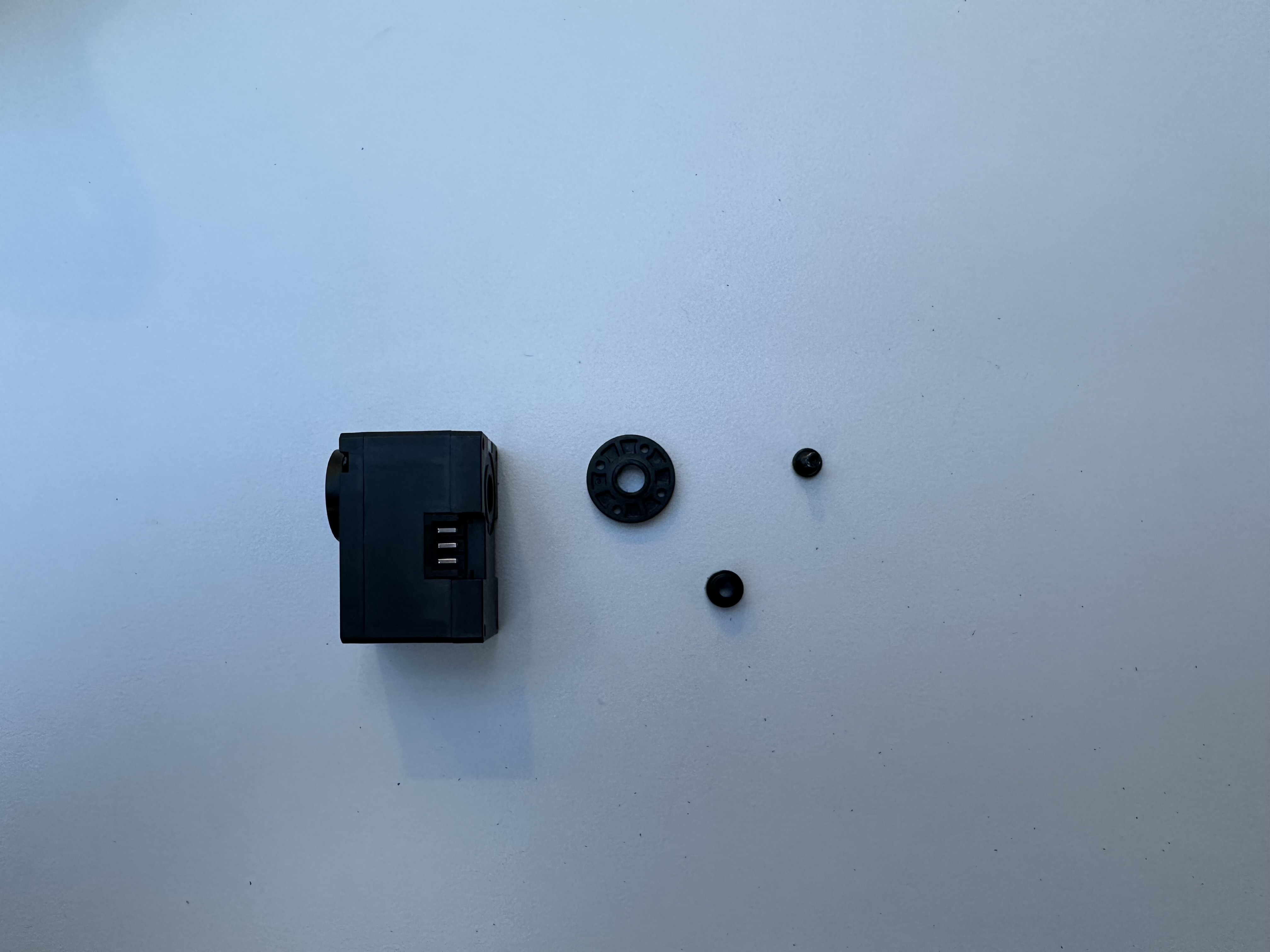
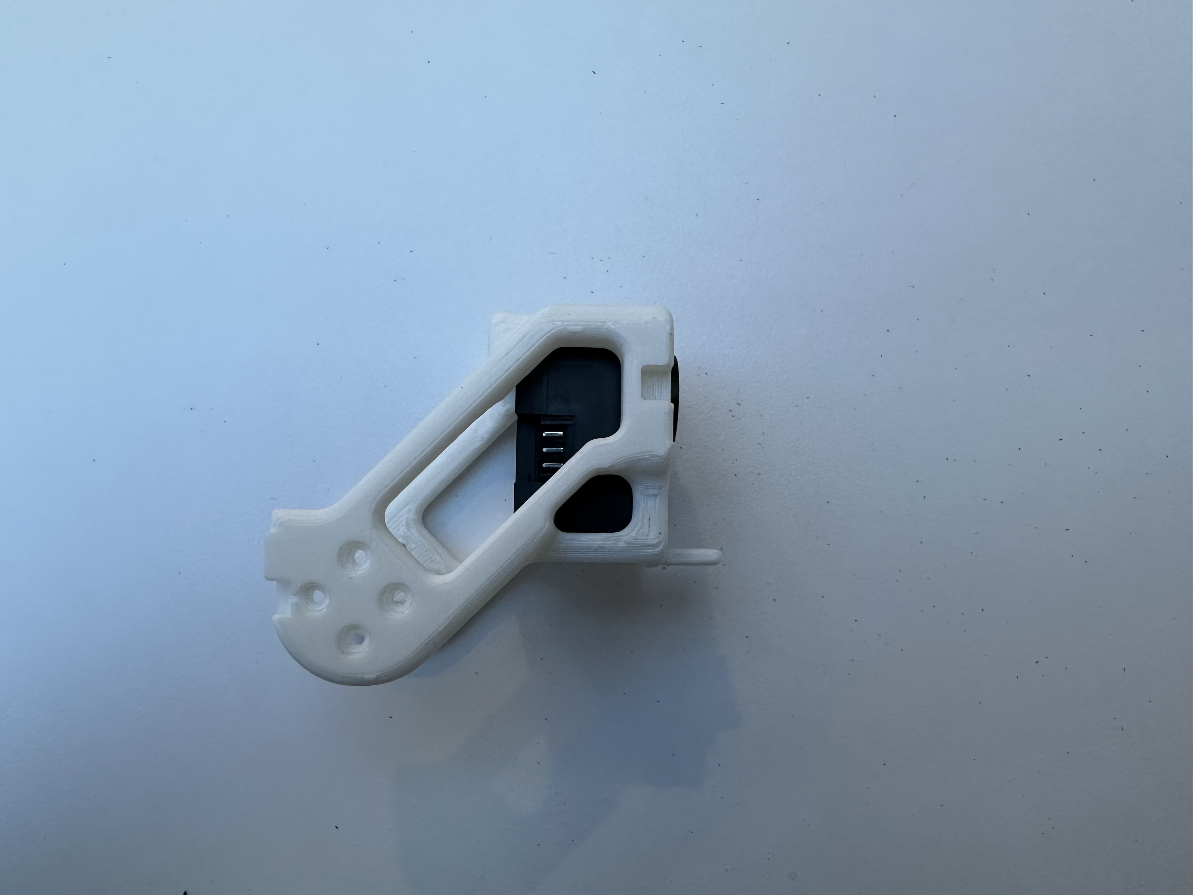
Take a Dynamixel motor, assemble an idler, and assign an ID 14 to the motor.
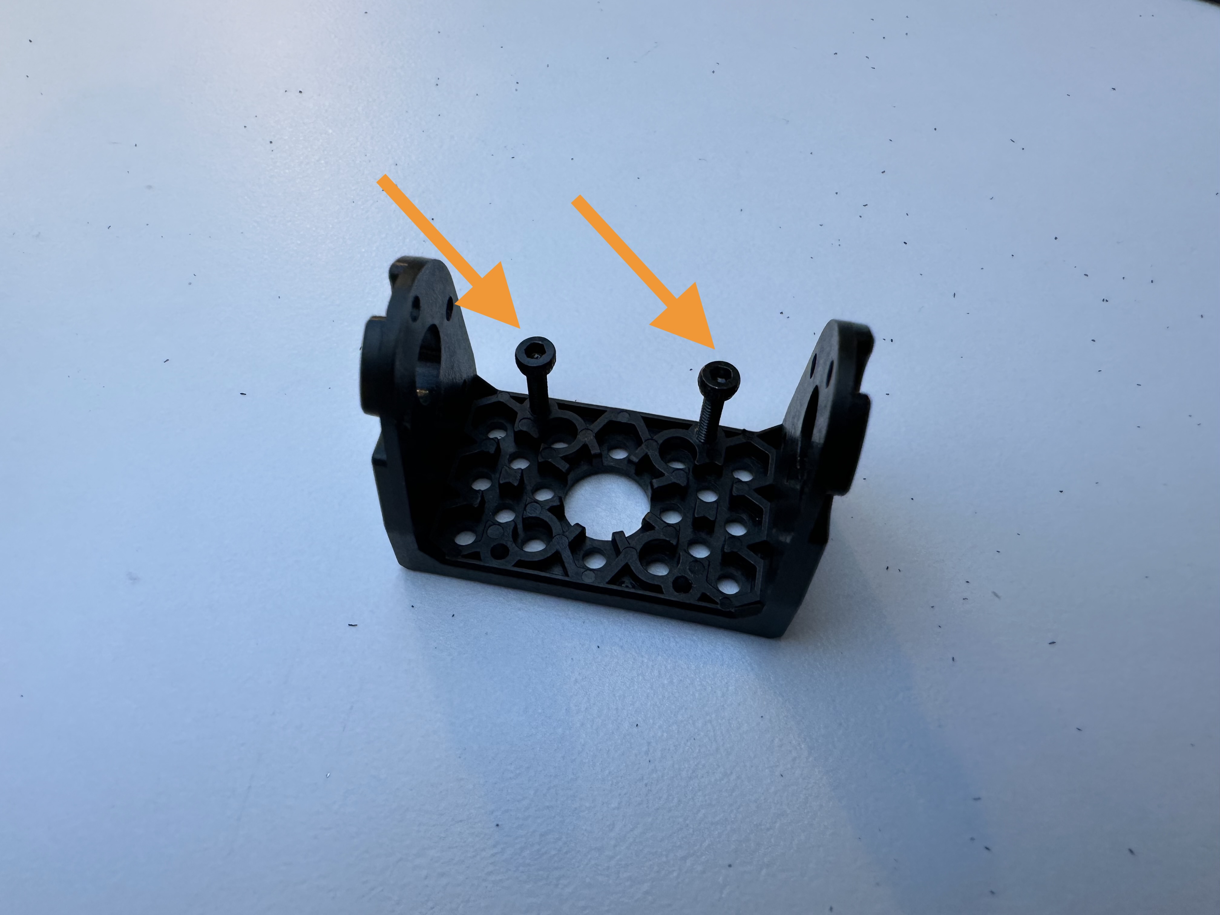
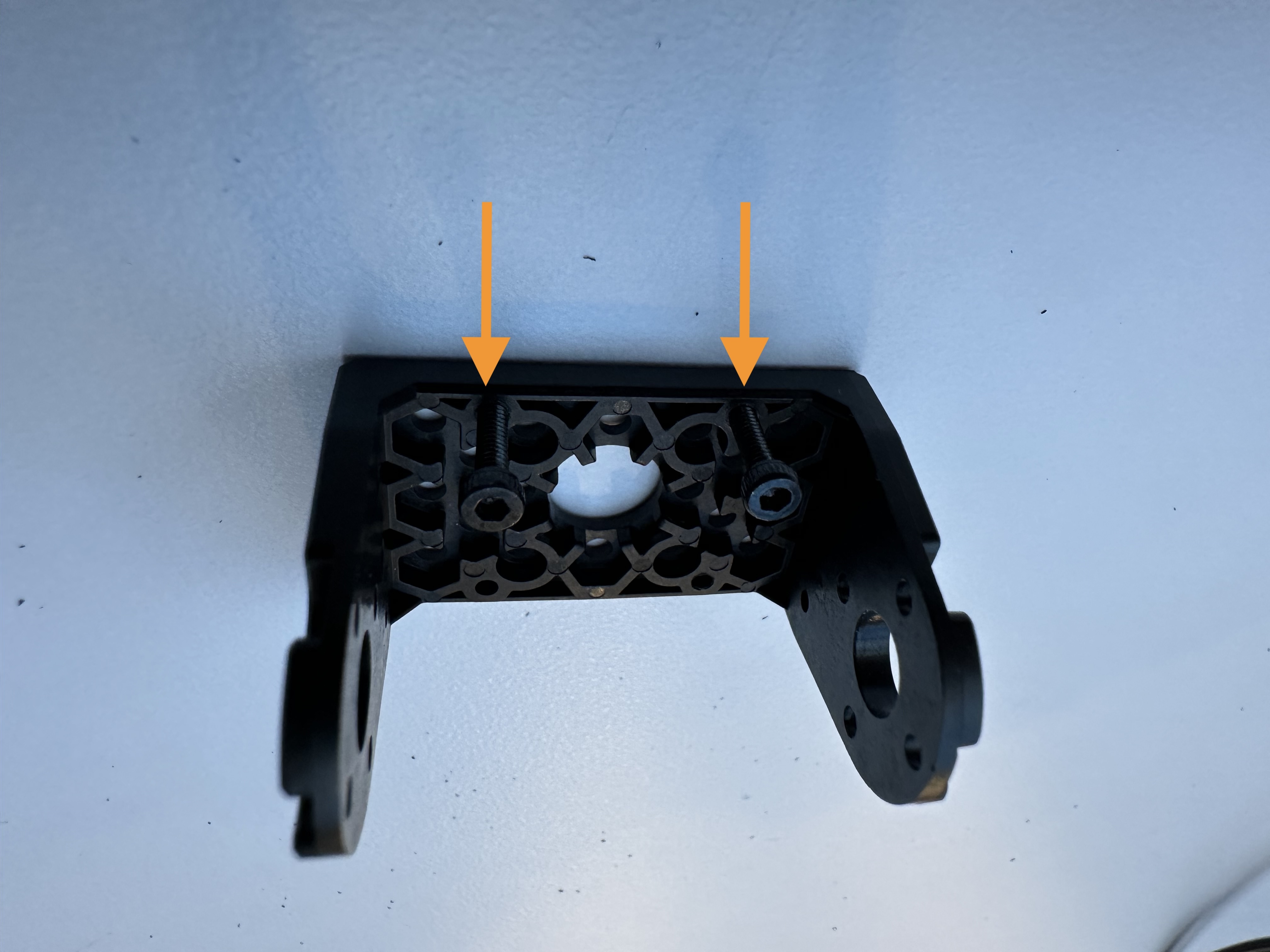
Then take a hinge frame and two M2 screws. Drive the screws to the hinge frame as shown below.
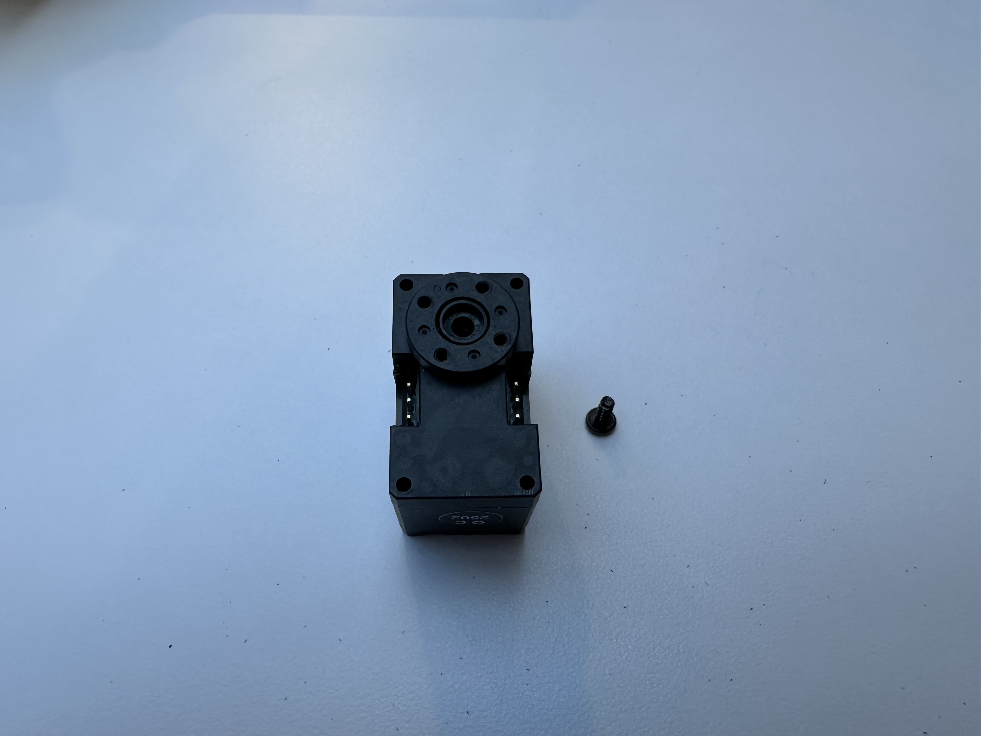
Take a Dynamixel motor, assign an ID 15 to it, plug one cable, and tighten it to the hinge frame.

Take the Dynamixel motor that is previously assembled with the idler, using short screws provided in the hinge frame kit to secure the motor to the hinge frame.
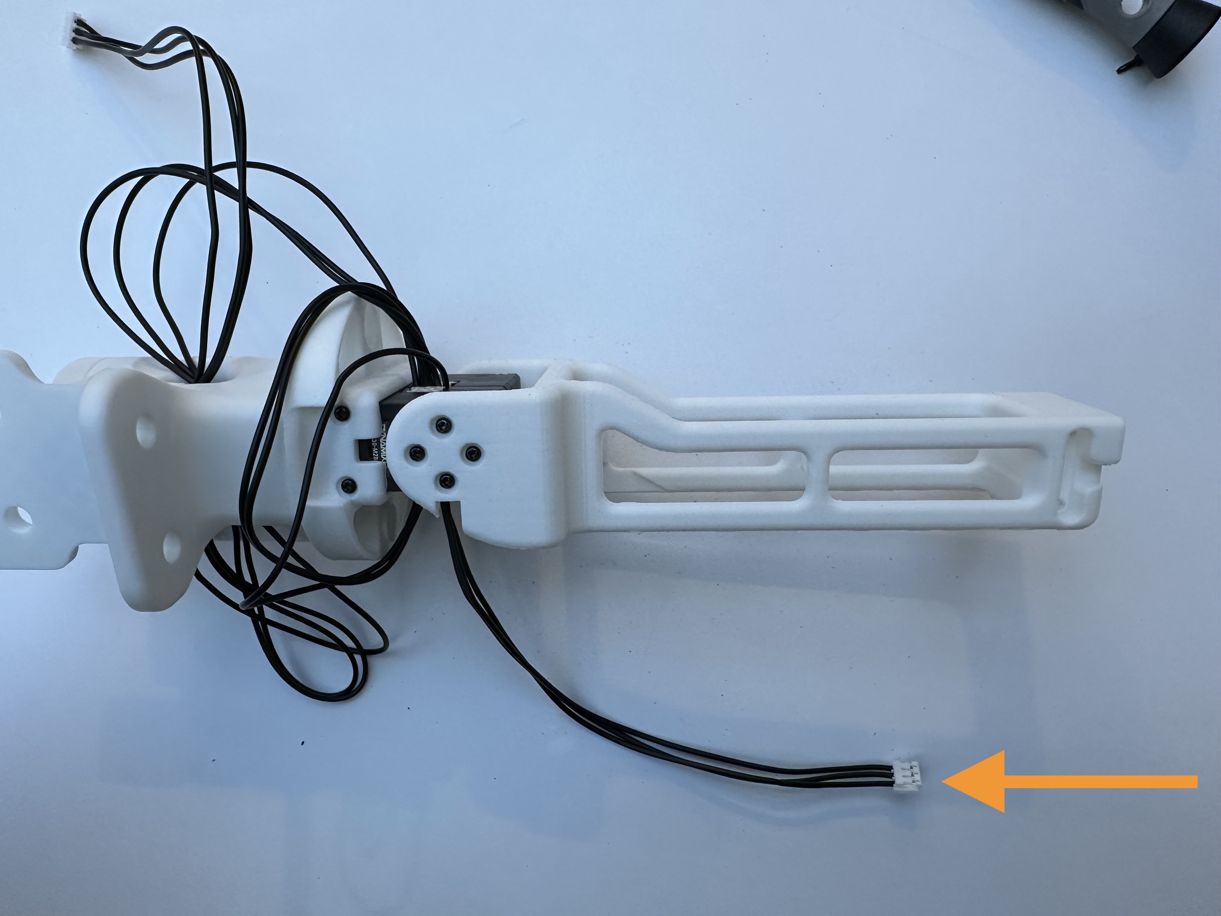
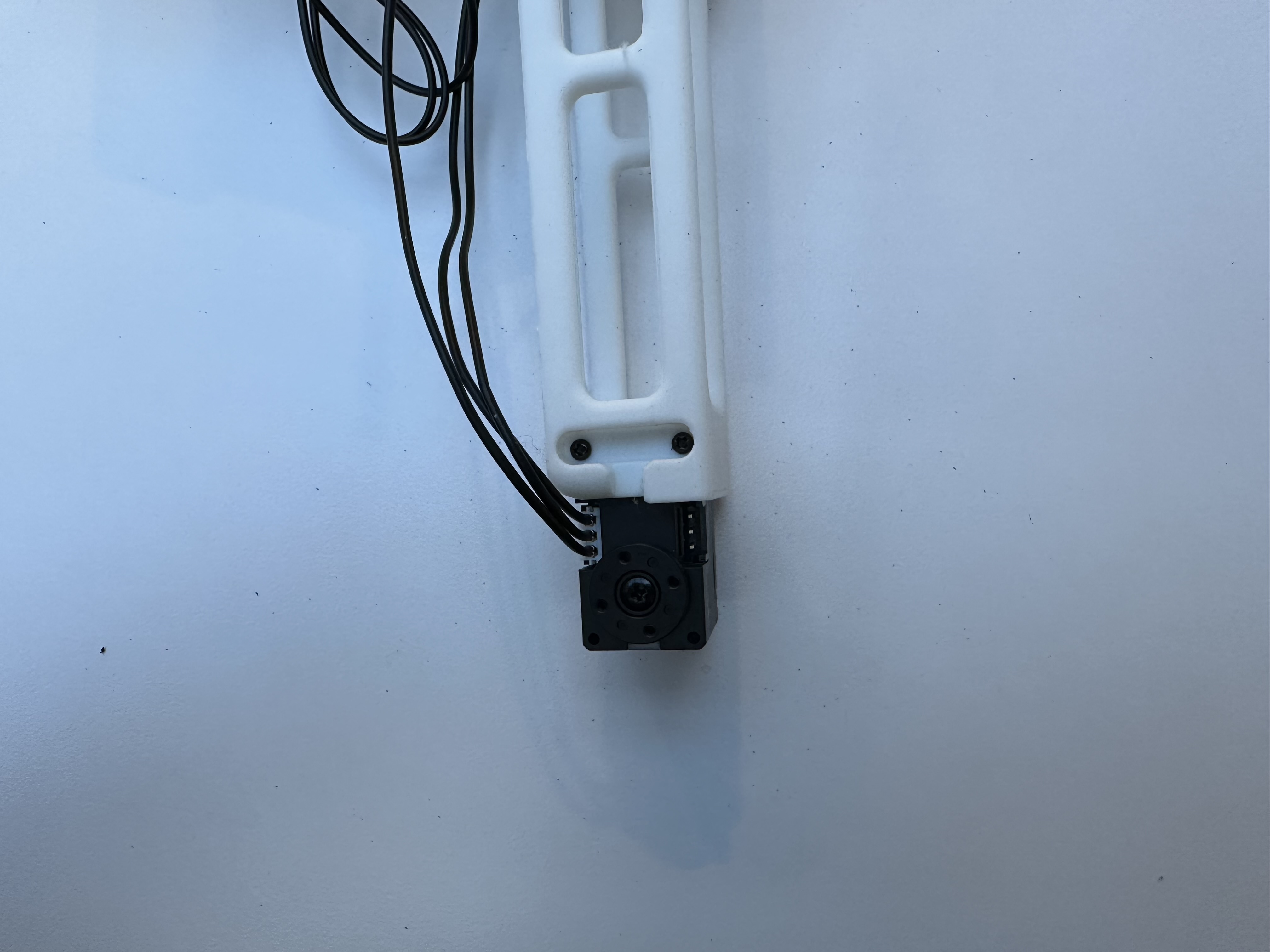
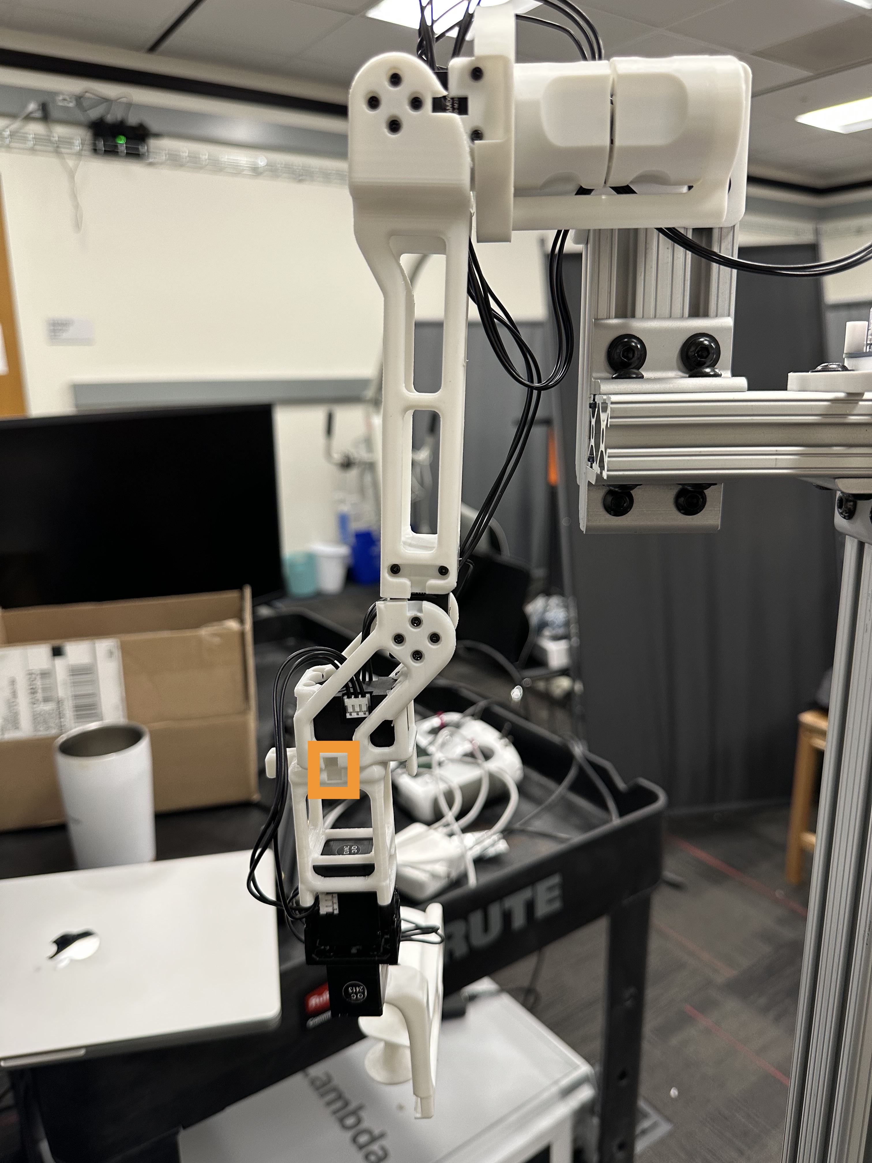
Take the previously assembled forearm and insert the wrist motor to the forearm. Tighten the screws and connect the motor with cables.
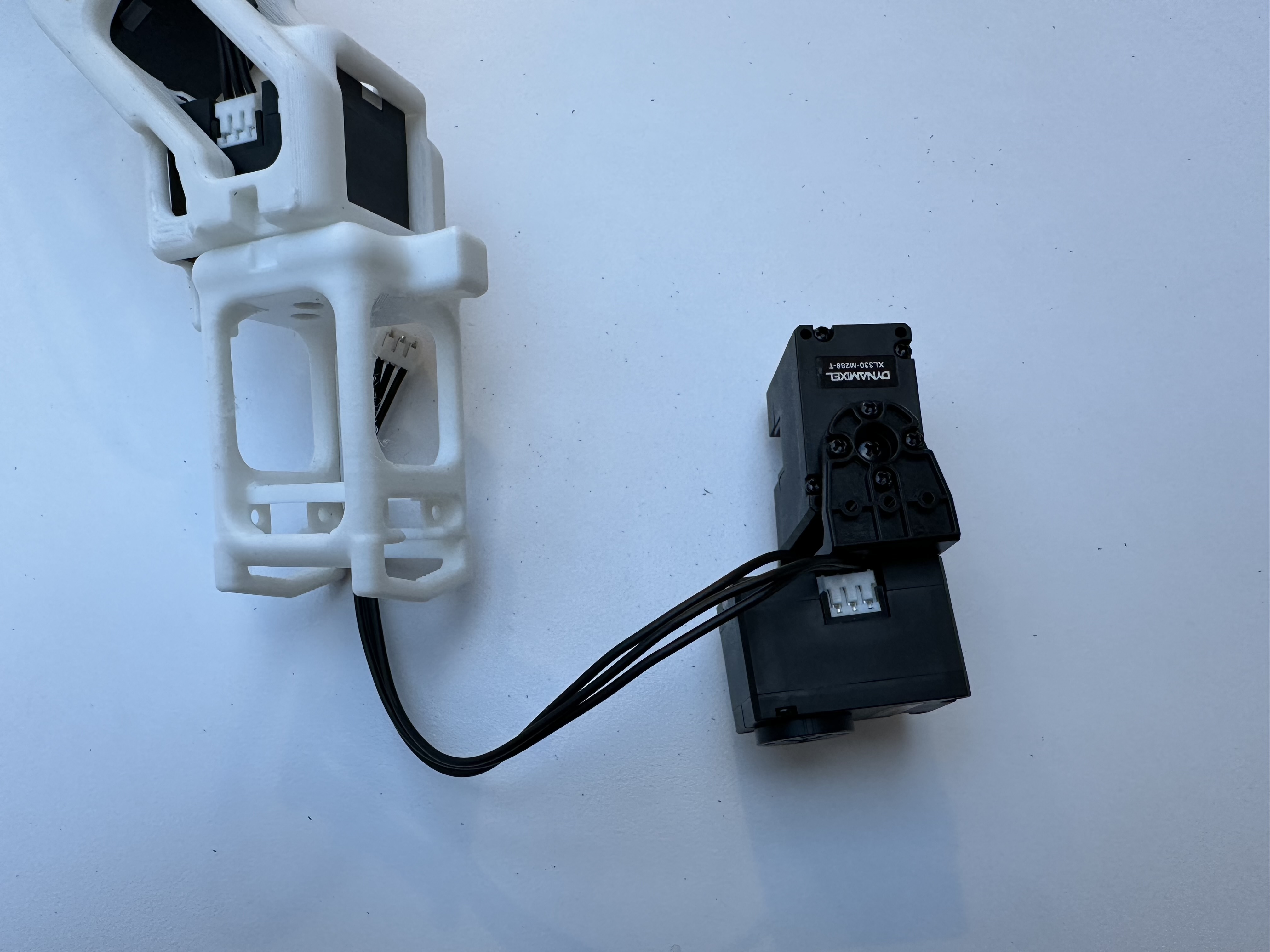
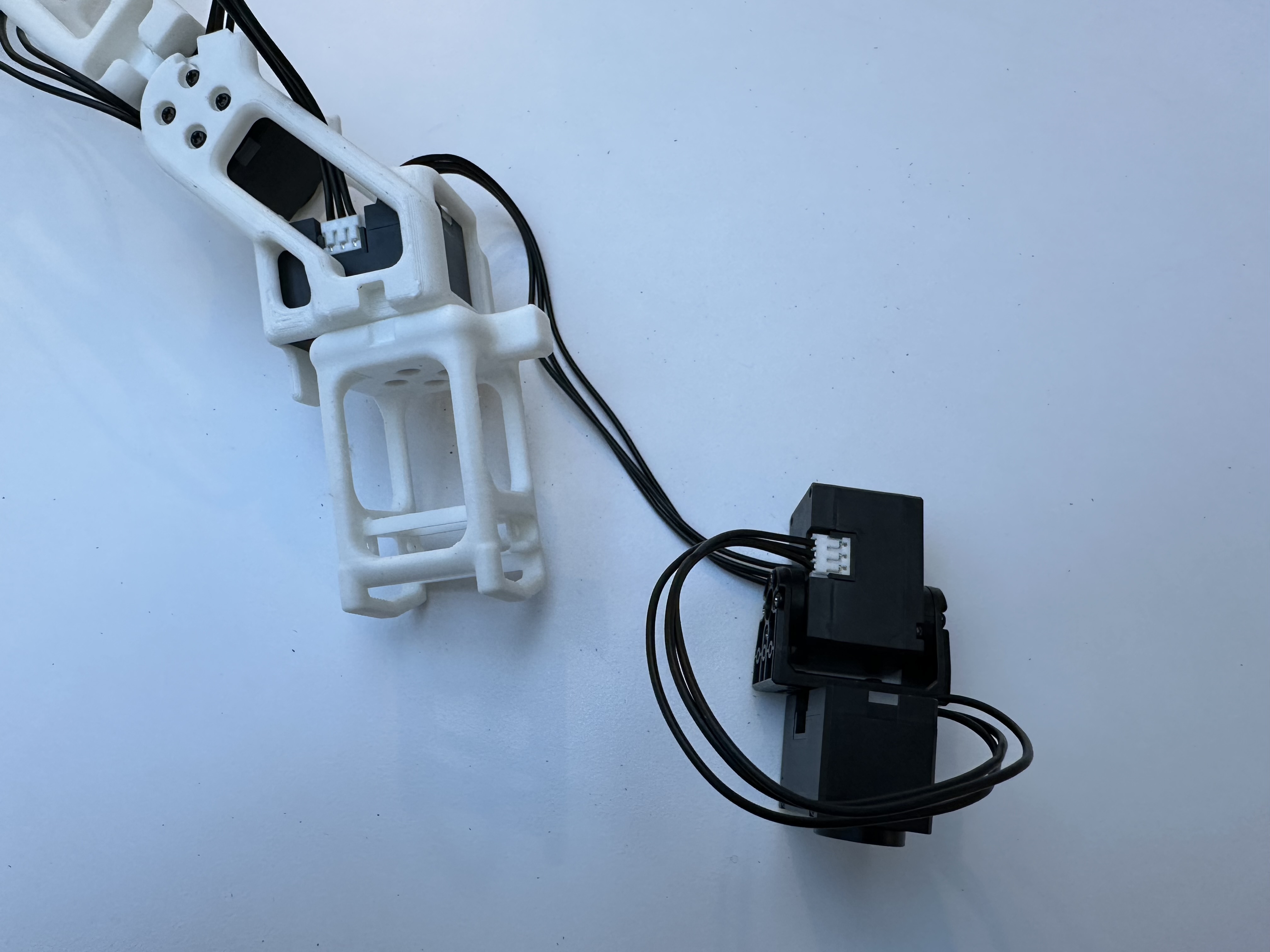
Make sure the forearm motor is adjusted to the provided shaft position.
Note
Make sure the shaft position is at 180 degrees when the arm is at the following configuration.
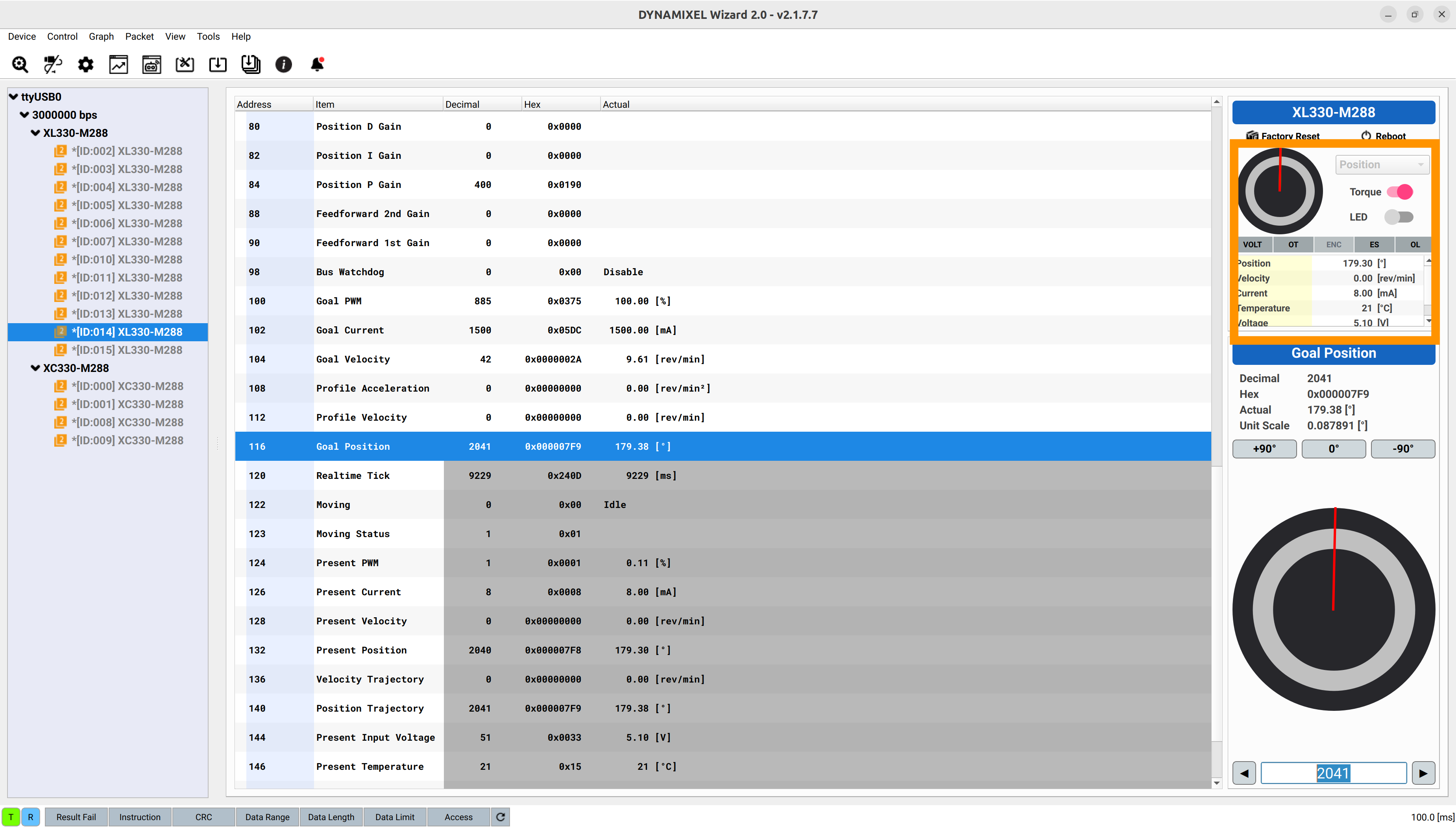
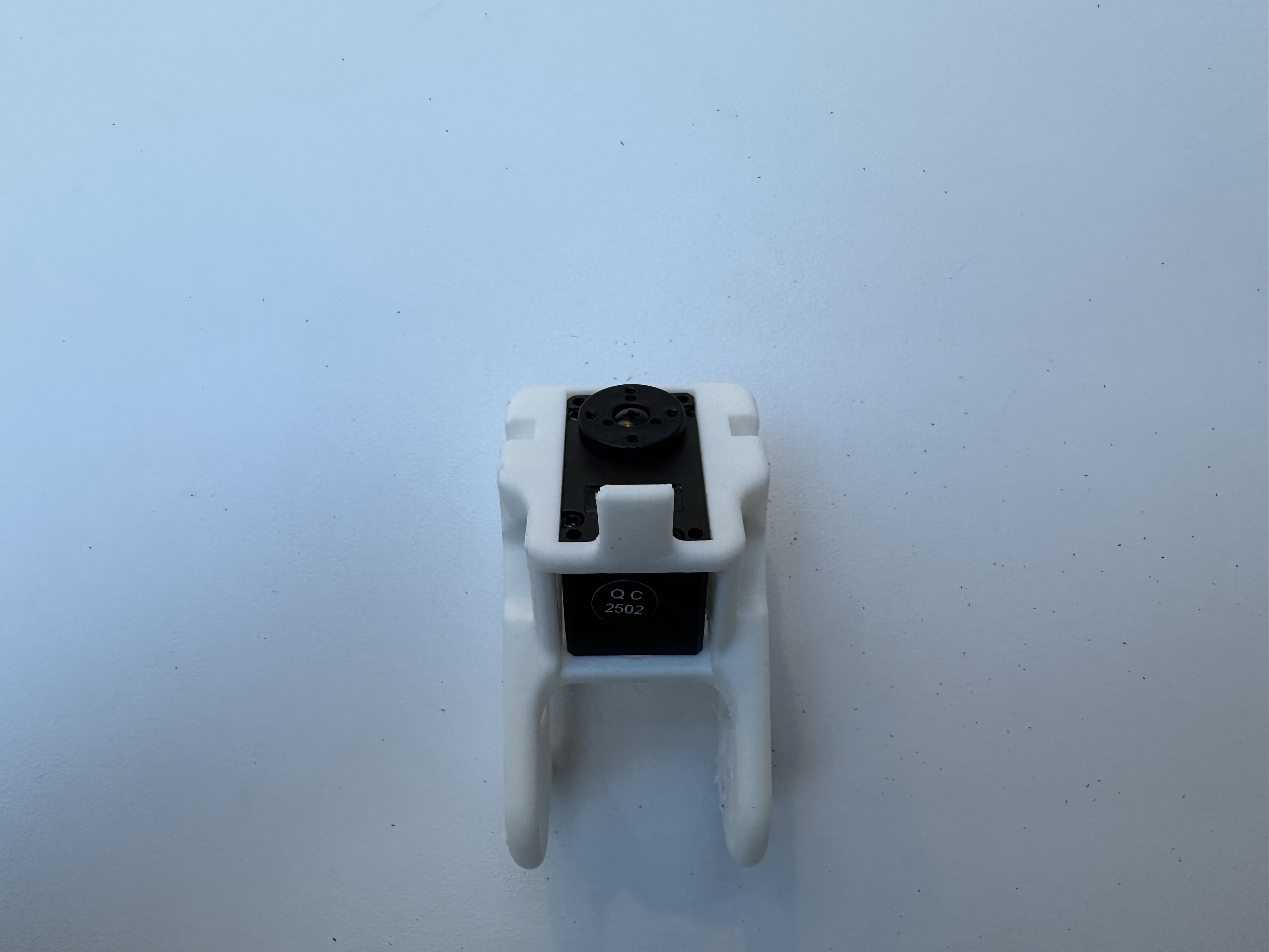
Take the assembled JoyCon holder and tighten it to the wrist motor. Make sure the wrist motor is adjusted to the provided shaft position.
Note
Make sure the shaft position is at 180 degrees when the arm is at the following configuration.
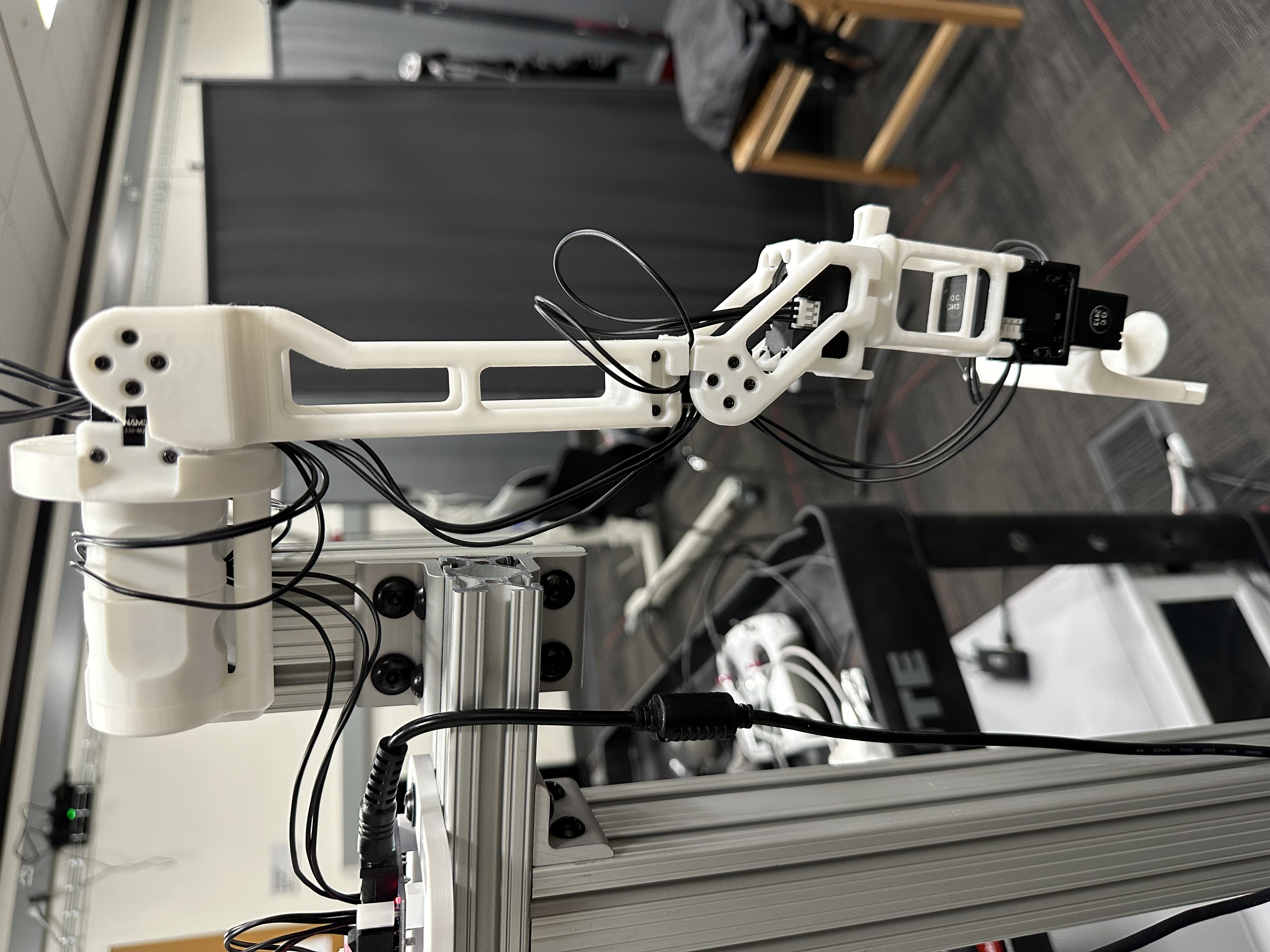
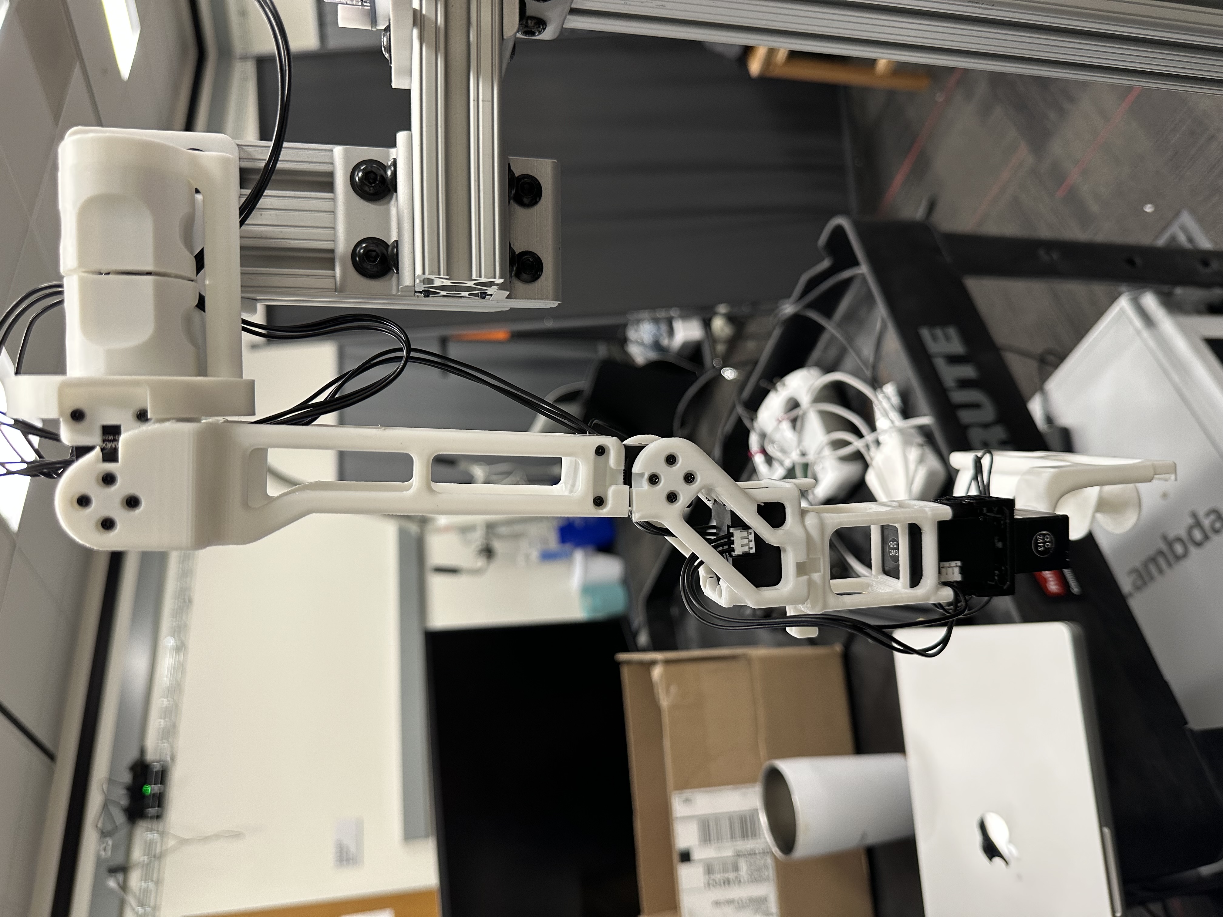
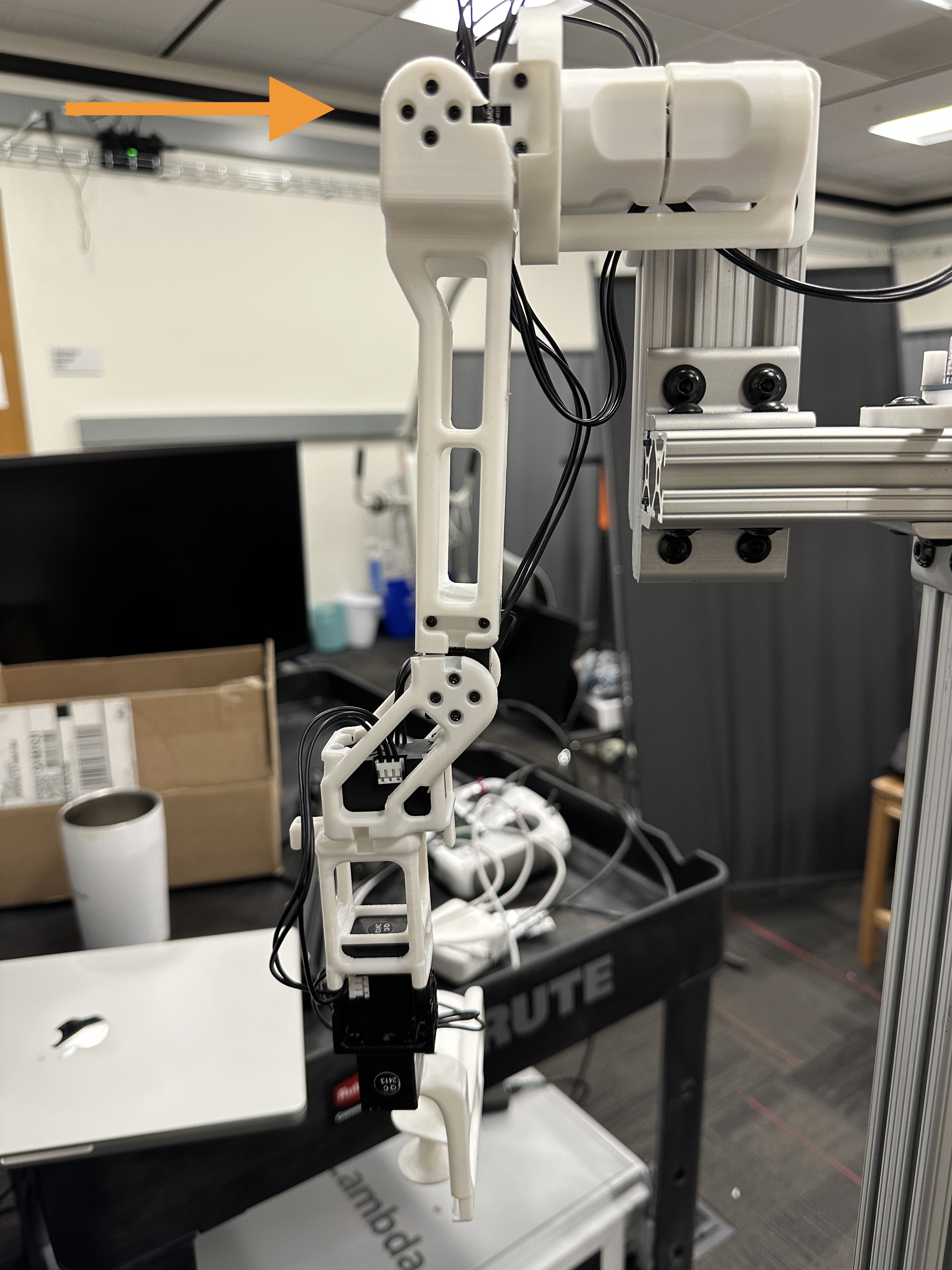
Now you have an assembled right arm!
Assemble the Left Arm#
The left arm can be assembled in a similar way. Notice the shaft positions of the shoulder roll motors are mirrored. Please ensure the shaft positions are at 90 degrees when the arm is at the following configuration.


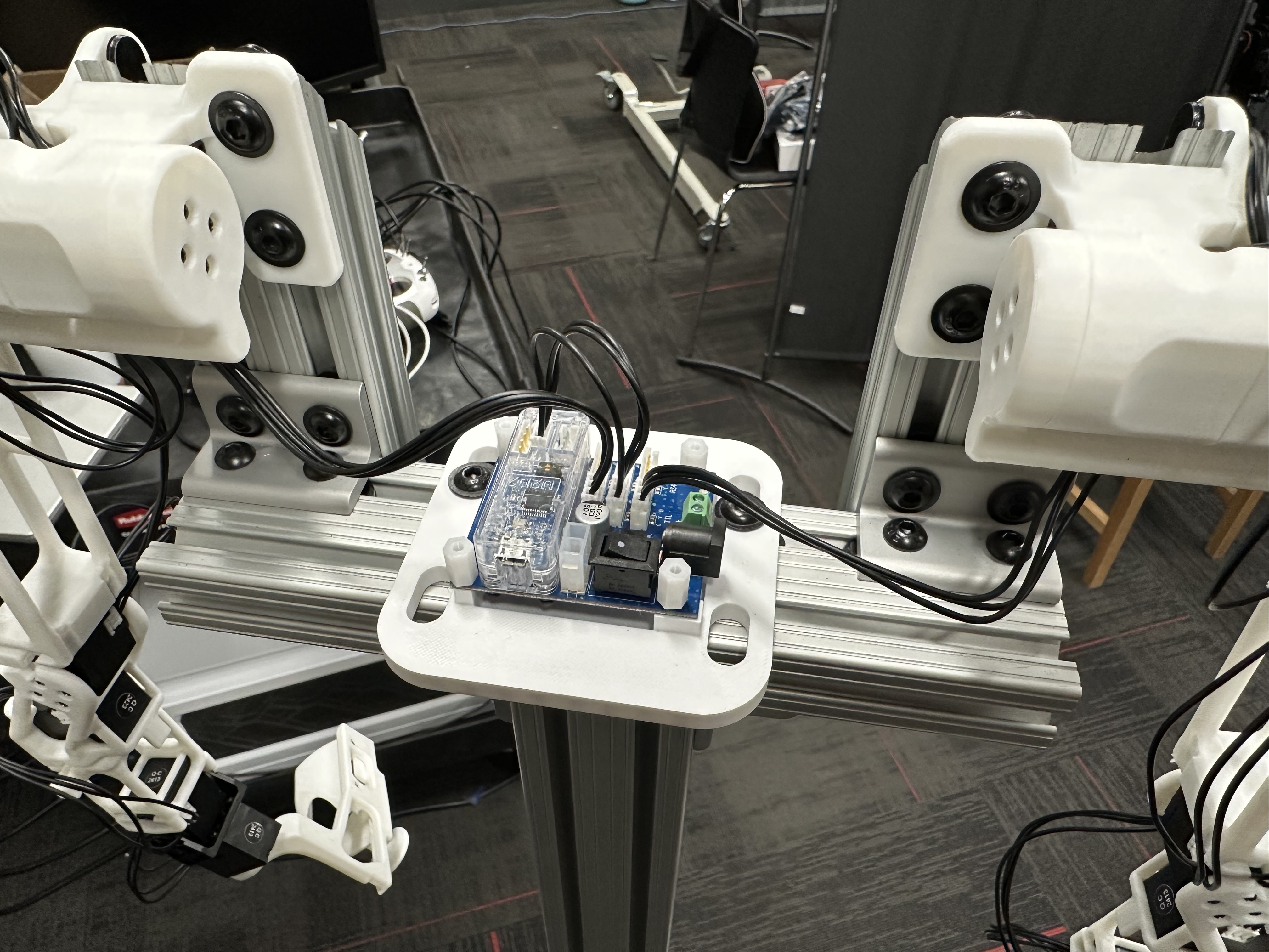
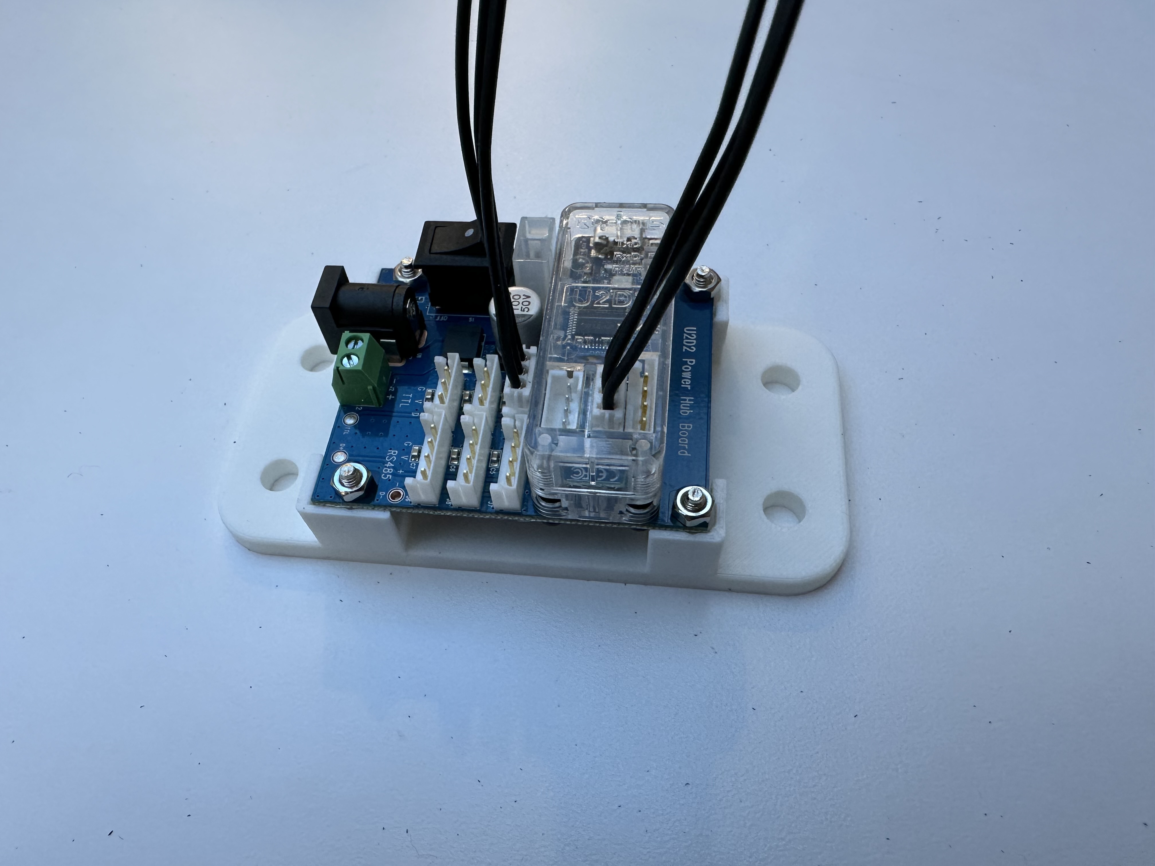
Assemble the U2D2 Mount#
Take the U2D2, power hub board, and the U2D2 mount u2d2_mount.obj.
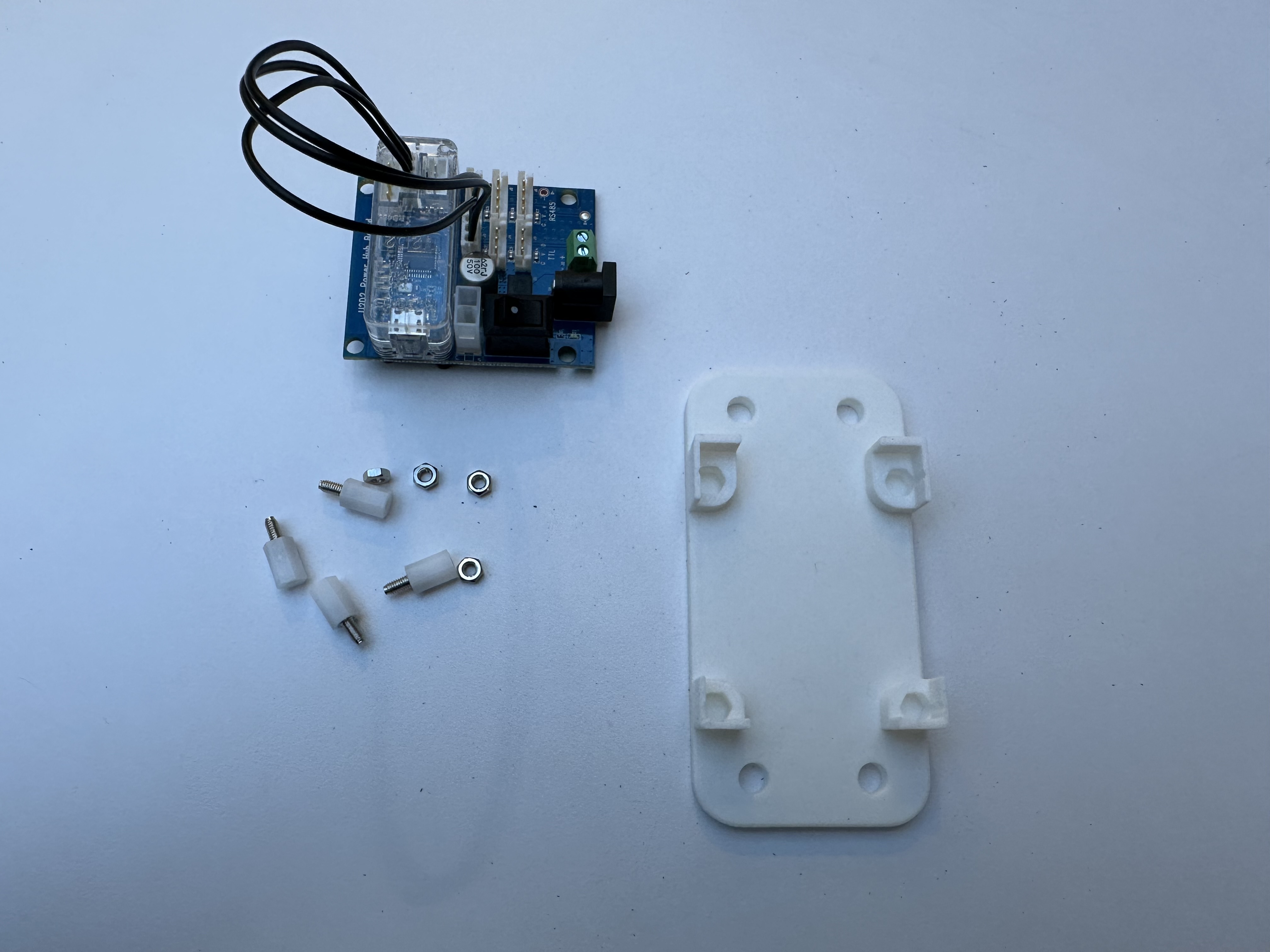
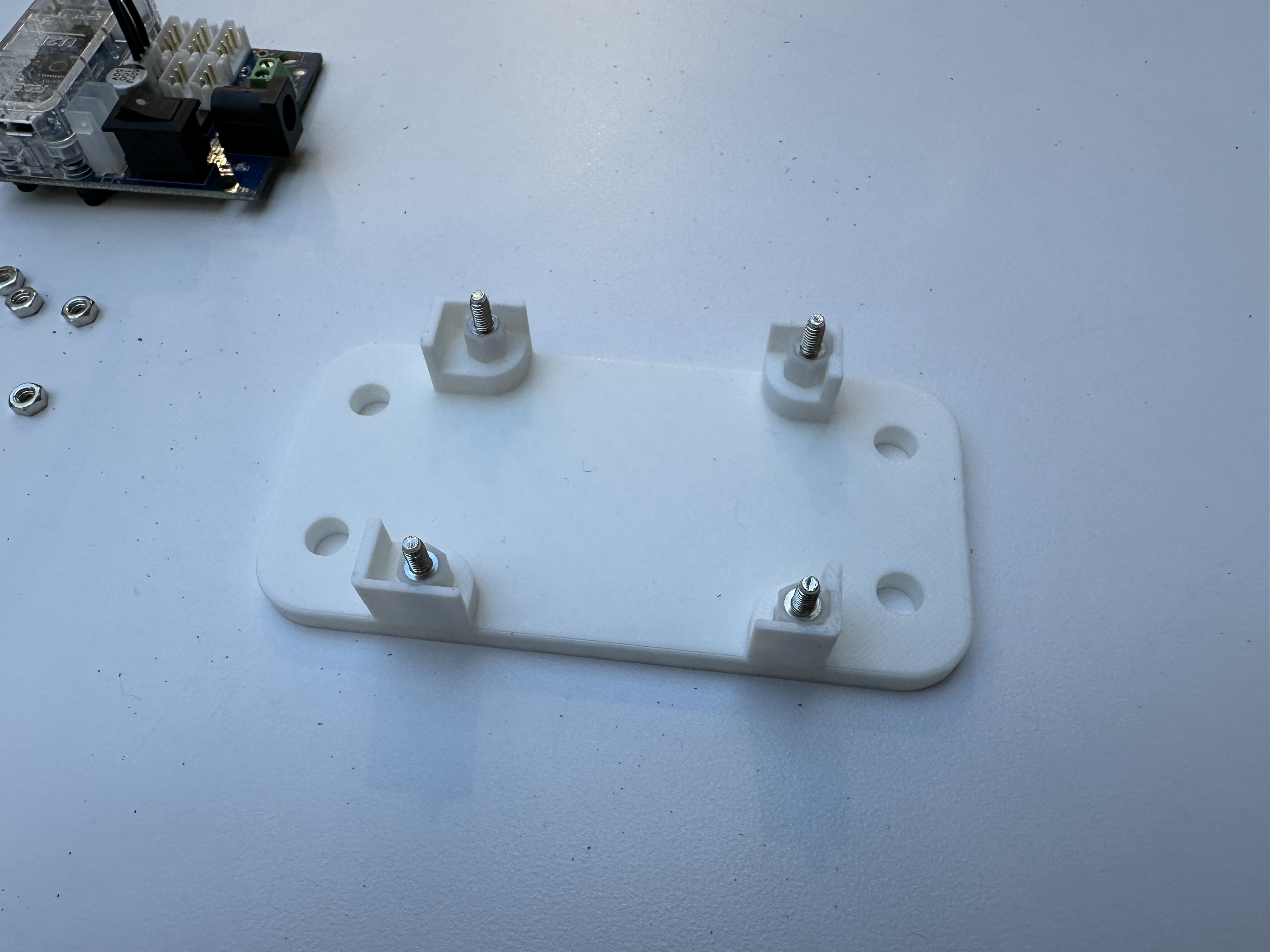
Put the four hex screws into the slots.
Insert the power hub board into the mount.
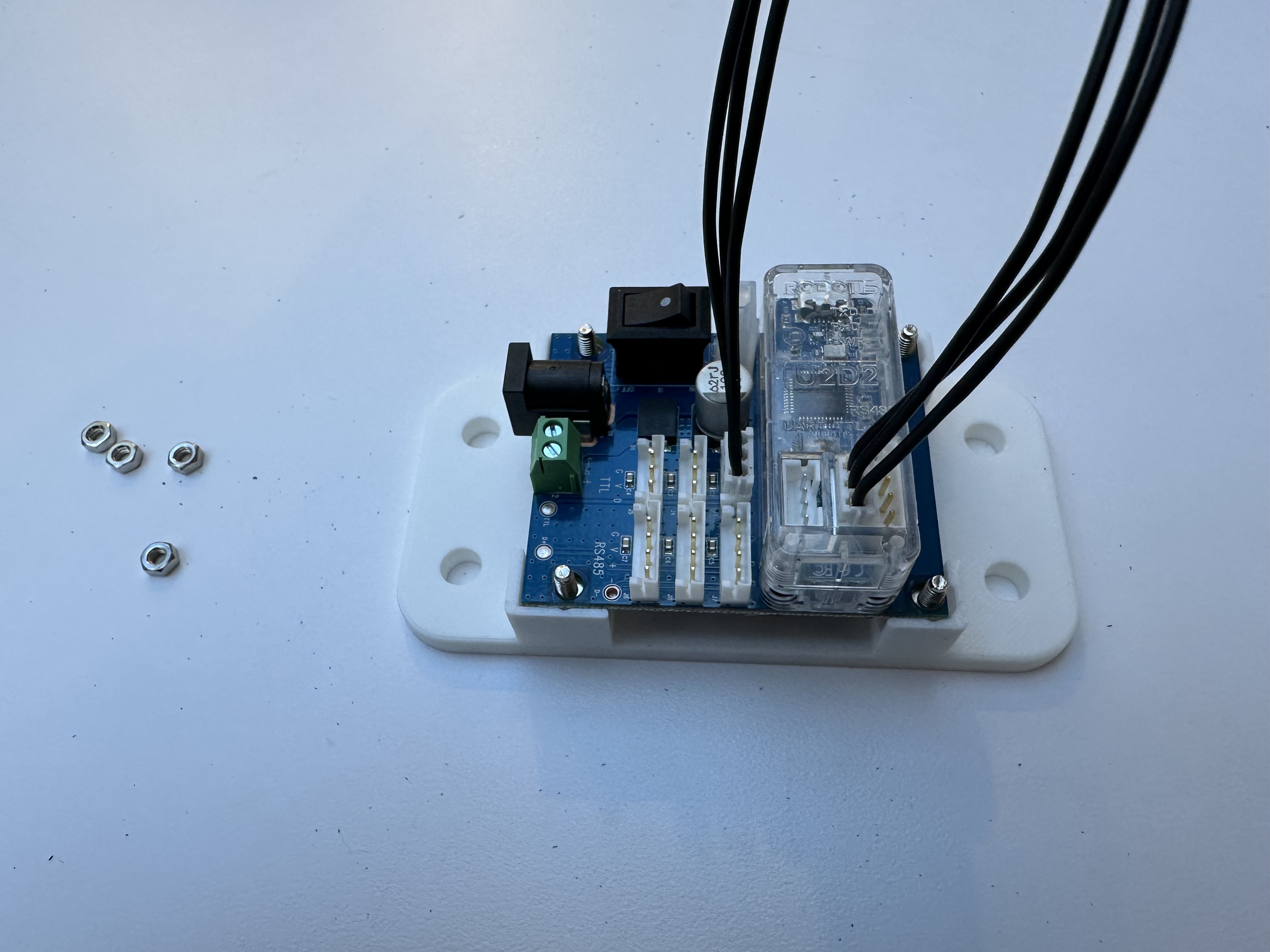
Finally tighten the screws to secure the U2D2 and power hub board.
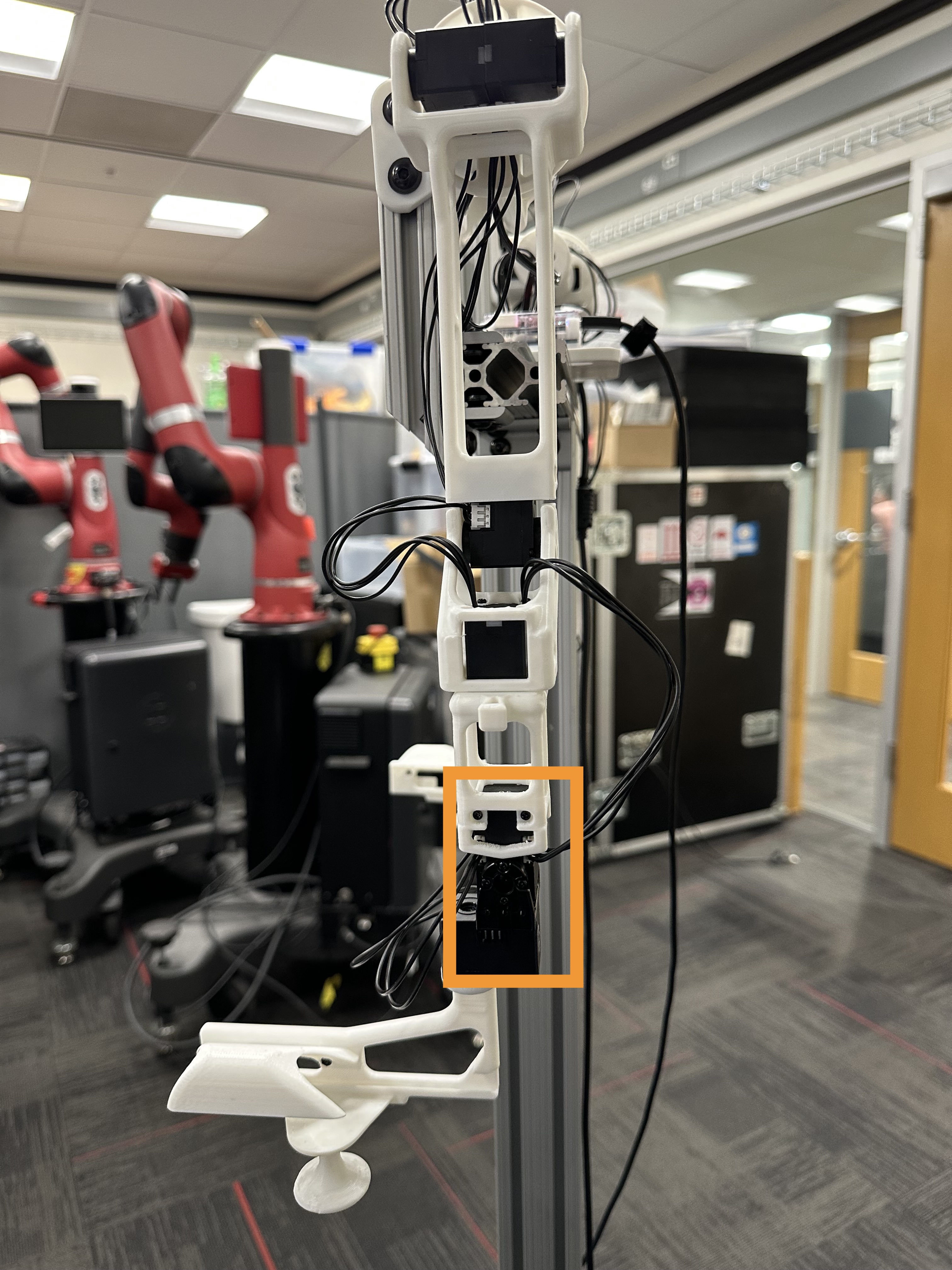
Put Everything on the T-Slot Extrusion#
Using screws and nuts to fix assembled components to the T-slot extrusion, as shown below.